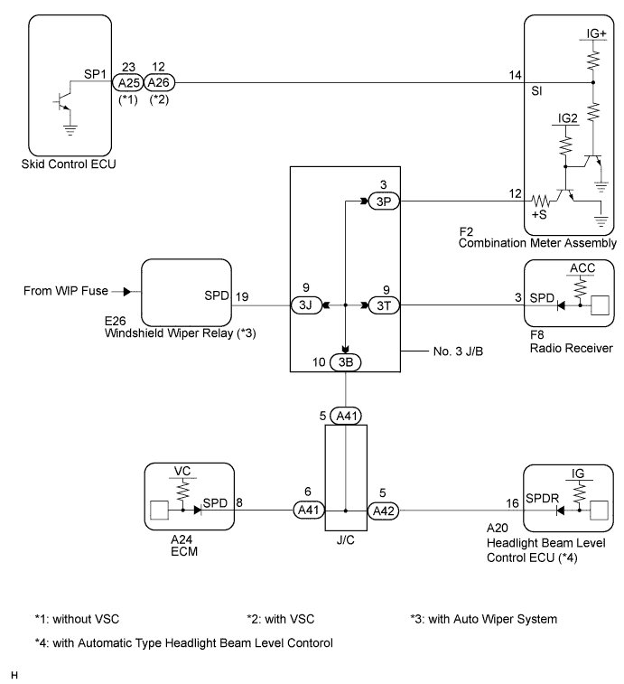
AUDIO AND VISUAL SYSTEM > Vehicle Speed Signal Circuit between Radio Receiver and Combination Meter |
| 2AZ-FE: |
| 2GR-FE: |
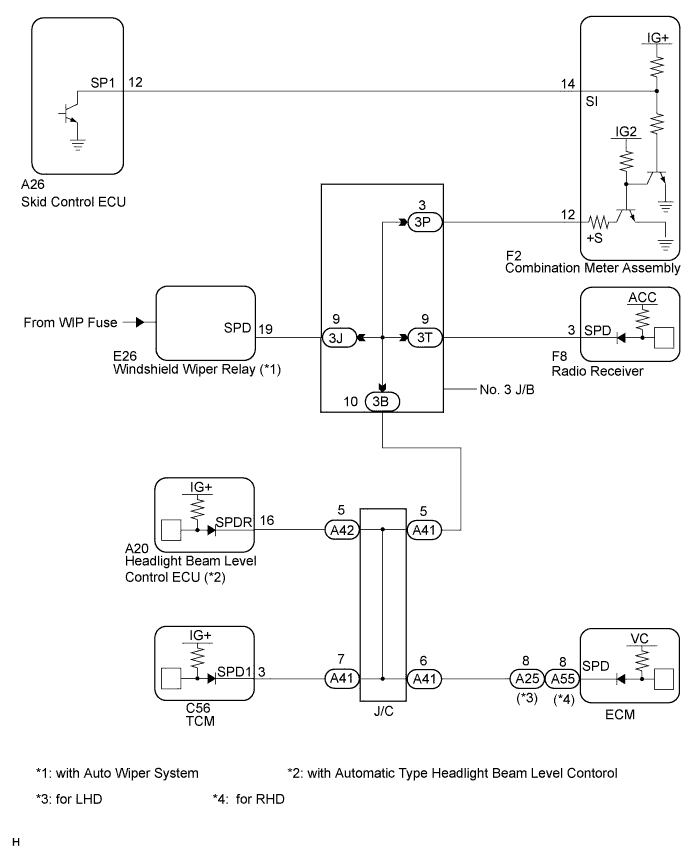
| 1.CHECK COMBINATION METER |
Inspect the circuits that send vehicle speed signals to the meter / gauge system (Click here).
During the inspection, if there is an instruction that indicates to go back to inspections for each system, proceed to the next step.
| NEXT | |
 |
| 2.CHECK HARNESS AND CONNECTOR (COMBINATION METER - RADIO RECEIVER) |
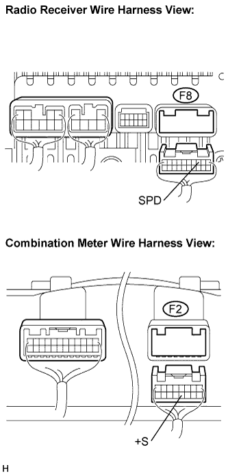 |
Disconnect the F2 connector from the combination meter assembly and the F8 connector from the radio receiver.
Measure the resistance according to the value(s) in the table below.
| Tester Connection | Condition | Specified Condition |
| F8-3 (SPD) - F2-12 (+S) | Always | Below 1 Ω |
|
| ||||
| OK | ||
 | ||
| ||
| 3.CHECK HARNESS AND CONNECTOR (RADIO RECEIVER - NO. 3 JUNCTION BLOCK) |
Disconnect the F8 connector from the radio receiver.
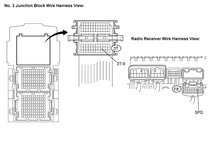
Disconnect the No. 3 junction block connector.
Measure the resistance according to the value(s) in the table below.
| Tester Connection | Condition | Specified Condition |
| F8-3 (SPD) - 3T-9 | Always | Below 1 Ω |
|
| ||||
| OK | ||
| ||
| ||

