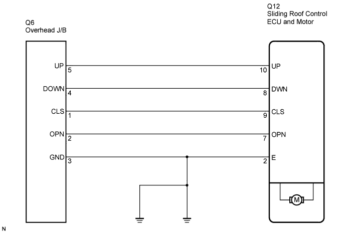
DTC B2341 Sensor (Motor) Failure |
DTC B2344 Position Failure |
| DTC No. | DTC Detection Condition | Trouble Area |
| B2341 | Sensor (motor) Failure |
|
| B2344 | Position Failure |
|
| 1.CHECK SLIDING ROOF FUNCTION |
Check the auto operation with the OPEN, DOWN, CLOSE, and UP switches (Click here).
|
| ||||
| OK | |
 |
| 2.DELETE DTC |
Delete the DTCs (Click here).
| NEXT | ||
 | ||
| ||
| 3.INITIALIZE SLIDING ROOF DRIVE GEAR SUB-ASSEMBLY (SLIDING ROOF CONTROL ECU) |
Check that the sliding roof drive gear sub-assembly can be initialized (Click here).
|
| ||||
| OK | |
|
| 4.CHECK SLIDING ROOF FUNCTION |
Check the auto operation with the OPEN, DOWN, CLOSE, and UP switches (Click here).
|
| ||||
| OK | |
|
| 5.DELETE DTC |
Delete the DTCs (Click here).
| NEXT | ||
| ||
| ||
| 6.CHECK WIRE HARNESS (SLIDING ROOF CONTROL ECU - ROOF CONSOLE BOX ASSEMBLY) |
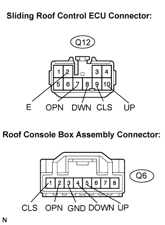 |
Disconnect the Q12 and Q6 connectors.
Measure the resistance according to the value(s) in the table below.
| Tester Connection | Condition | Specified Condition |
| Q12-2 (E) - Q6-3 (GND) | Always | Below 1 Ω |
| Q12-7 (OPN) - Q6-2 (OPN) | Always | Below 1 Ω |
| Q12-8 (DWN) - Q6-4 (DOWN) | Always | Below 1 Ω |
| Q12-9 (CLS) - Q6-1 (CLS) | Always | Below 1 Ω |
| Q12-10 (UP) - Q6-5 (UP) | Always | Below 1 Ω |
| Q6-1 (CLS) - Body ground | Always | 10 kΩ or higher |
| Q6-2 (OPN) - Body ground | Always | 10 kΩ or higher |
| Q6-3 (GND) - Body ground | Always | Below 1 Ω |
| Q6-4 (DOWN) - Body ground | Always | 10 kΩ or higher |
| Q6-5 (UP) - Body ground | Always | 10 kΩ or higher |
|
| ||||
| OK | |
|
| 7.INSPECT ROOF CONSOLE BOX ASSEMBLY (SLIDING ROOF CONTROL SWITCH) |
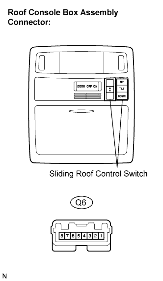 |
Remove the roof console box assembly.
Measure the resistance according to the value(s) in the table below.
| Tester Connection | Switch Position | Specified Condition |
| Q6-1 (CLS) - Q6-3 (GND) | CLOSE | Below 100 Ω |
| Q6-2 (OPN) - Q6-3 (GND) | OPEN | Below 100 Ω |
| Q6-4 (DOWN) - Q6-3 (GND) | DOWN | Below 100 Ω |
| Q6-5 (UP) - Q6-3 (GND) | UP | Below 100 Ω |
| Q6-1 (CLS) - Q6-3 (GND) | OPEN | 1 kΩ or higher |
| Q6-2 (OPN) - Q6-3 (GND) | CLOSE | 1 kΩ or higher |
| Q6-4 (DOWN) - Q6-3 (GND) | UP | 1 kΩ or higher |
| Q6-5 (UP) - Q6-3 (GND) | DOWN | 1 kΩ or higher |
|
| ||||
| OK | ||
| ||
| ||

