Home › Audio / Visual / Telematics › AUDIO / VIDEO › AUDIO AND VISUAL SYSTEM(for Radio and Display Type) › 2011.10–2013.07
RM19V0EQ _56 Audio / Visual / Telematics _014599 AUDIO / VIDEO _0074081 AUDIO AND VISUAL SYSTEM(for Radio and Display Type) J

AUDIO / VIDEO  AUDIO AND VISUAL SYSTEM(for Radio and Display Type)  Reverse Signal Circuit  


DESCRIPTION

for U760E:

The radio and display receiver assembly receives a reverse signal from the park/neutral position switch assembly.

for EB62:

The radio and display receiver assembly receives a reverse signal from the back-up light switch assembly.

WIRING DIAGRAM
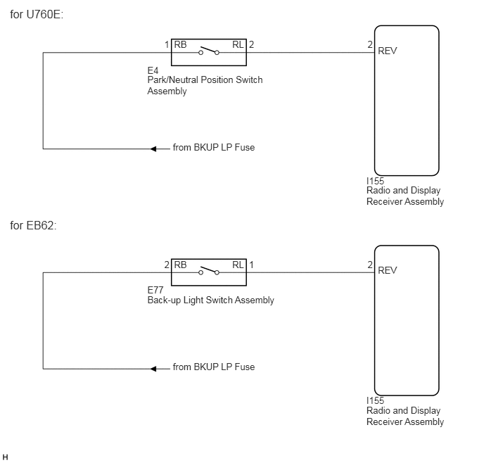
E235675E01
5.426,2.733 6.643,3.078 1.217,0.345 10 Radio and Display Receiver Assembly 5.426,2.594 5.734,2.749 0.308,0.154 10 I155 2.182,1.096 3.97,1.441 1.788,0.345 10 Park/Neutral Position Switch Assembly 0.147,0.105 0.971,0.311 0.824,0.206 12 for U760E: 0.147,3.234 0.956,3.441 0.809,0.206 12 for EB62: 2.182,0.957 2.49,1.112 0.308,0.154 10 E4 2.56,2.09 3.853,2.245 1.293,0.154 10 from BKUP LP Fuse 5.443,0.577 5.563,0.731 0.12,0.154 10 2 3.687,0.577 3.808,0.731 0.12,0.154 10 2 3.439,0.577 3.648,0.731 0.209,0.154 10 RL 2.433,0.577 2.553,0.731 0.12,0.154 10 1 2.577,0.577 2.798,0.731 0.221,0.154 10 RB 5.596,0.667 5.918,0.821 0.322,0.154 10 REV 5.426,5.988 6.643,6.333 1.217,0.345 10 Radio and Display Receiver Assembly 5.426,5.849 5.734,6.004 0.308,0.154 10 I155 2.182,4.351 4.153,4.547 1.971,0.196 10 Back-up Light Switch Assembly 2.182,4.213 2.49,4.367 0.308,0.154 10 E77 2.56,5.346 3.853,5.5 1.293,0.154 10 from BKUP LP Fuse 5.443,3.832 5.563,3.987 0.12,0.154 10 2 3.687,3.832 3.808,3.987 0.12,0.154 10 1 3.439,3.832 3.648,3.987 0.209,0.154 10 RL 2.433,3.832 2.553,3.987 0.12,0.154 10 2 2.577,3.832 2.798,3.987 0.221,0.154 10 RB 5.596,3.922 5.918,4.077 0.322,0.154 10 REV

PROCEDURE

1.CHECK HARNESS AND CONNECTOR (REVERSE SIGNAL)
a.

Disconnect the radio and display receiver assembly connector.


b.

Measure the voltage according to the value(s) in the table below.

Standard Voltage:
Tester Connection Condition Specified Condition
I155-2 (REV) - Body ground Ignition switch ON
Shift lever in R
11 to 14 V
I155-2 (REV) - Body ground Ignition switch ON
Shift lever in any position other than R
Below 1 V


c.

Proceed to the next step based on the check result.

Result:
Result Proceed to
OK A
NG (for U760E) B
NG (for EB62) C


A

B

2.CHECK HARNESS AND CONNECTOR (RADIO AND DISPLAY RECEIVER ASSEMBLY - PARK/NEUTRAL POSITION SWITCH ASSEMBLY)

C

4.CHECK HARNESS AND CONNECTOR (RADIO AND DISPLAY RECEIVER ASSEMBLY - BACK-UP LIGHT SWITCH ASSEMBLY)
2.CHECK HARNESS AND CONNECTOR (RADIO AND DISPLAY RECEIVER ASSEMBLY - PARK/NEUTRAL POSITION SWITCH ASSEMBLY)
a.

Disconnect the radio and display receiver assembly connector.


b.

Disconnect the park/neutral position switch assembly connector.


c.

Measure the resistance according to the value(s) in the table below.

Standard Resistance:
Tester Connection Condition Specified Condition
I155-2 (REV) - E4-2 (RL) Always Below 1 Ω
I155-2 (REV) - Body ground Always 10 kΩ or higher


Result:
Proceed to
OK
NG


OK

3.CHECK HARNESS AND CONNECTOR (PARK/NEUTRAL POSITION SWITCH ASSEMBLY - BATTERY)

NG

REPAIR OR REPLACE HARNESS OR CONNECTOR

3.CHECK HARNESS AND CONNECTOR (PARK/NEUTRAL POSITION SWITCH ASSEMBLY - BATTERY)
a.

Disconnect the park/neutral position switch assembly connector.


b.

Measure the voltage according to the value(s) in the table below.

Standard Voltage:
Tester Connection Condition Specified Condition
E4-1 (RB) - Body ground Ignition switch ON 11 to 14 V


Result:
Proceed to
OK
NG


OK

NG

REPAIR OR REPLACE HARNESS OR CONNECTOR

4.CHECK HARNESS AND CONNECTOR (RADIO AND DISPLAY RECEIVER ASSEMBLY - BACK-UP LIGHT SWITCH ASSEMBLY)
a.

Disconnect the radio and display receiver assembly connector.


b.

Disconnect the back-up light switch assembly connector.


c.

Measure the resistance according to the value(s) in the table below.

Standard Resistance:
Tester Connection Condition Specified Condition
I155-2 (REV) - E77-1 (RL) Always Below 1 Ω
I155-2 (REV) - Body ground Always 10 kΩ or higher


Result:
Proceed to
OK
NG


OK

5.CHECK HARNESS AND CONNECTOR (BACK-UP LIGHT SWITCH ASSEMBLY - BATTERY)

NG

REPAIR OR REPLACE HARNESS OR CONNECTOR

5.CHECK HARNESS AND CONNECTOR (BACK-UP LIGHT SWITCH ASSEMBLY - BATTERY)
a.

Disconnect the back-up light switch assembly connector.


b.

Measure the voltage according to the value(s) in the table below.

Standard Voltage:
Tester Connection Condition Specified Condition
E77-2 (RB) - Body ground Ignition switch ON 11 to 14 V


Result:
Proceed to
OK
NG


OK

NG

REPAIR OR REPLACE HARNESS OR CONNECTOR