NAVIGATION / MULTI INFO DISPLAY NAVIGATION SYSTEM(for HDD) Illumination Circuit
DESCRIPTION
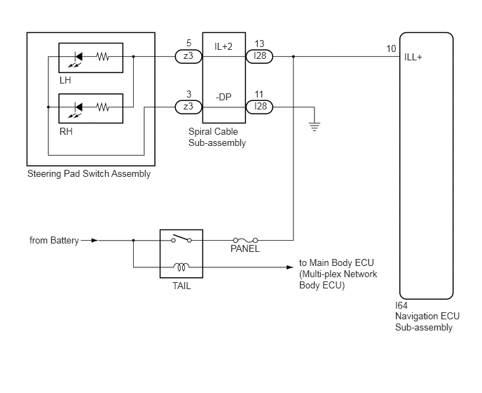
Power is supplied to the navigation ECU sub-assembly and steering pad switch assembly illumination when the light control switch is in the tail or head position.
WIRING DIAGRAM
CAUTION / NOTICE / HINT
- NOTICE:
- ·
The vehicle is equipped with a Supplemental Restraint System (SRS) which includes components such as airbags. Before servicing (including removal or installation of parts), be sure to read the precaution for Supplemental Restraint System (w/ VSC) (See page Vehicle Interior>SUPPLEMENTAL RESTRAINT SYSTEMS>AIRBAG SYSTEM(w/ VSC)>PRECAUTION).
·The vehicle is equipped with a Supplemental Restraint System (SRS) which includes components such as airbags. Before servicing (including removal or installation of parts), be sure to read the precaution for Supplemental Restraint System (w/o VSC) (See page Vehicle Interior>SUPPLEMENTAL RESTRAINT SYSTEMS>AIRBAG SYSTEM(w/o VSC)>PRECAUTION).
·Inspect the fuse for circuits related to this system before performing the following inspection procedure.
PROCEDURE
Check if the illumination for the navigation ECU sub-assembly, steering pad switch assembly, heater control switch or others (hazard switch, transmission control switch, etc.) comes on when the light control switch is turned to the head or tail position.
- Result:
Result Proceed to Illumination comes on for all components except steering pad switch assembly. A Illumination comes on for all components except navigation ECU sub-assembly. B No illumination comes on (navigation ECU sub-assembly, hazard switch, heater control switch, etc.). C
A
B
C
Disconnect the spiral cable sub-assembly connector.
Measure the voltage according to the value(s) in the table below.
- Standard Voltage:
Tester Connection Condition Specified Condition I28-13 (IL+2) - Body ground Light control switch in the tail or head position 11 to 14 V
- Result:
Proceed to OK NG
OK
NG
Disconnect the steering pad switch assembly connector.
Connect a battery positive (+) lead to terminal IL+2 and a negative (-) lead to terminal -DP of the steering pad switch assembly connector.
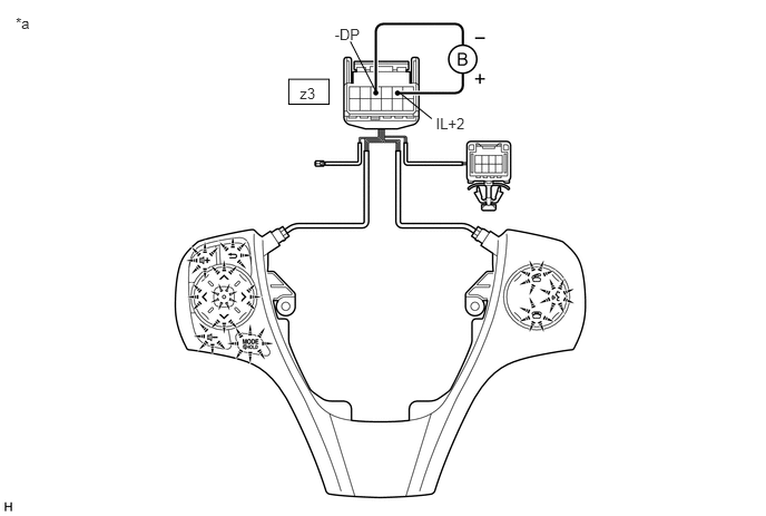
| *a | Component without harness connected
(Steering Pad Switch Assembly) |
- | - |
Check if the illumination for the steering pad switch assembly comes on.
- OK:
Illumination for the steering pad switch assembly comes on.
- Result:
Proceed to OK NG
OK
NG
Disconnect the steering pad switch assembly connector.
Disconnect the spiral cable sub-assembly connector.
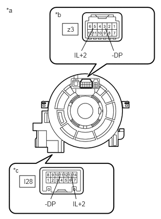
| *a | Component without harness connected
(Spiral Cable Sub-assembly) |
| *b | Steering Pad Switch Assembly Side |
| *c | Vehicle Side |
Measure the resistance according to the value(s) in the table below.
- Standard Resistance:
Tester Connection Condition Specified Condition z3-5 (IL+2) - I28-13 (IL+2) Center Below 1 Ω 2.5 rotations to the left 2.5 rotations to the right z3-3 (-DP) - I28-11 (-DP) Center Below 1 Ω 2.5 rotations to the left 2.5 rotations to the right
After setting the spiral cable sub-assembly to the center position, rotate the spiral cable sub-assembly 2.5 times clockwise. Then while rotating the spiral cable sub-assembly 5 times counterclockwise, measure the resistance as shown in the table below.
- Standard Resistance:
Tester Connection Condition Specified Condition z3-5 (IL+2) - I28-13 (IL+2) Always Below 3 Ω z3-3 (-DP) - I28-11 (-DP) Always Below 3 Ω
- NOTICE:
- ·
Press and hold the lock located in the center of the spiral cable sub-assembly to rotate the spiral cable sub-assembly.
·The spiral cable sub-assembly is an important part of the SRS airbag system. Incorrect removal or installation of the spiral cable sub-assembly may prevent the airbag from deploying. Refer to the pages shown in the brackets.
·As the spiral cable sub-assembly may break, do not rotate the spiral cable sub-assembly more than the specified amount.
- HINT:
- ·
Removal
Click hereVehicle Interior>SUPPLEMENTAL RESTRAINT SYSTEMS>SPIRAL CABLE>REMOVAL
·Installation
Click hereVehicle Interior>SUPPLEMENTAL RESTRAINT SYSTEMS>SPIRAL CABLE>INSTALLATION
- Result:
Proceed to OK NG
OK
NG
Disconnect the navigation ECU sub-assembly connector.
Measure the voltage according to the value(s) in the table below.
- Standard Voltage:
Tester Connection Condition Specified Condition I64-10 (ILL+) - Body ground Light control switch in the tail or head position 11 to 14 V
- Result:
Proceed to OK NG
OK
NG