NAVIGATION / MULTI INFO DISPLAY NAVIGATION SYSTEM(for HDD) Steering Pad Switch Circuit
DESCRIPTION
This circuit sends an operation signal from the steering pad switch assembly to the navigation ECU sub-assembly.
If there is an open in the circuit, the audio system cannot be operated using the steering pad switch assembly.
If there is a short in the circuit, the same condition as when a switch is continuously depressed occurs.
Therefore, the navigation ECU sub-assembly cannot be operated using the steering pad switch assembly, and also the navigation ECU sub-assembly itself cannot function.
WIRING DIAGRAM
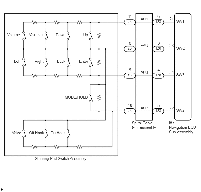
CAUTION / NOTICE / HINT
- NOTICE:
- ·
The vehicle is equipped with a Supplemental Restraint System (SRS) which includes components such as airbags. Before servicing (including removal or installation of parts), be sure to read the precaution for Supplemental Restraint System (w/ VSC) (See page Vehicle Interior>SUPPLEMENTAL RESTRAINT SYSTEMS>AIRBAG SYSTEM(w/ VSC)>PRECAUTION).
·The vehicle is equipped with a Supplemental Restraint System (SRS) which includes components such as airbags. Before servicing (including removal or installation of parts), be sure to read the precaution for Supplemental Restraint System (w/o VSC) (See page Vehicle Interior>SUPPLEMENTAL RESTRAINT SYSTEMS>AIRBAG SYSTEM(w/o VSC)>PRECAUTION).
PROCEDURE
Disconnect the navigation ECU sub-assembly connector.
Measure the resistance according to the value(s) in the table below.
- Standard Resistance:
Tester Connection Condition Specified Condition I67-21 (SW1) - I67-23 (SWG) No switch pushed 95 to 105 kΩ Up switch pushed Below 2.5 Ω Down switch pushed 313 to 345 Ω Volume+ switch pushed 950 to 1050 Ω Volume- switch pushed 2955 to 3265 Ω I67-22 (SW2) - I67-23 (SWG) No switch pushed 95 to 105 kΩ MODE/HOLD switch pushed Below 2.5 Ω On hook switch pushed 313 to 345 Ω Off hook switch pushed 950 to 1050 Ω Voice switch pushed 2955 to 3265 Ω I67-24 (SW3) - I67-23 (SWG) No switch pushed 95 to 105 kΩ Enter switch pushed Below 2.5 Ω Back switch pushed 313 to 345 Ω Right switch pushed 950 to 1050 Ω Left switch pushed 2955 to 3265 Ω
- Result:
Proceed to OK NG
OK
NG
Disconnect the steering pad switch assembly connector.
Measure the resistance according to the value(s) in the table below.
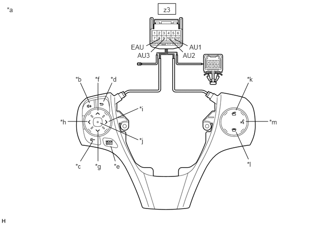
| *a | Component without harness connected
(Steering Pad Switch Assembly) |
*b | Volume+ |
| *c | Volume- | *d | Back |
| *e | MODE/HOLD | *f | Up |
| *g | Down | *h | Left |
| *i | Right | *j | Enter |
| *k | Off hook | *l | On hook |
| *m | Voice | - | - |
- Standard Resistance:
Tester Connection Condition Specified Condition z3-11 (AU1) - z3-8 (EAU) No switch pushed 95 to 105 kΩ Up switch pushed Below 2.5 Ω Down switch pushed 313 to 345 Ω Volume+ switch pushed 950 to 1050 Ω Volume- switch pushed 2955 to 3265 Ω z3-10 (AU2) - z3-8 (EAU) No switch pushed 95 to 105 kΩ MODE/HOLD switch pushed Below 2.5 Ω On hook switch pushed 313 to 345 Ω Off hook switch pushed 950 to 1050 Ω Voice switch pushed 2955 to 3265 Ω z3-9 (AU3) - z3-8 (EAU) No switch pushed 95 to 105 kΩ Enter switch pushed Below 2.5 Ω Back switch pushed 313 to 345 Ω Right switch pushed 950 to 1050 Ω Left switch pushed 2955 to 3265 Ω
- Result:
Proceed to OK NG
OK
NG
Disconnect the steering pad switch assembly connector.
Disconnect the spiral cable sub-assembly connector.
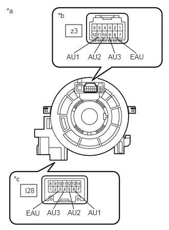
| *a | Component without harness connected
(Spiral Cable Sub-assembly) |
| *b | Steering Pad Switch Assembly Side |
| *c | Vehicle Side |
Measure the resistance according to the value(s) in the table below.
- Standard Resistance:
Tester Connection Condition Specified Condition z3-8 (EAU) - I28-3 (EAU) Center Below 1 Ω 2.5 rotations to the left 2.5 rotations to the right z3-11 (AU1) - I28-6 (AU1) Center Below 1 Ω 2.5 rotations to the left 2.5 rotations to the right z3-10 (AU2) - I28-5 (AU2) Center Below 1 Ω 2.5 rotations to the left 2.5 rotations to the right z3-9 (AU3) - I28-4 (AU3) Center Below 1 Ω 2.5 rotations to the left 2.5 rotations to the right
After setting the spiral cable sub-assembly to the center position, rotate the spiral cable sub-assembly 2.5 times clockwise. Then while rotating the spiral cable sub-assembly 5 times counterclockwise, measure the resistance as shown in the table below.
- Standard Resistance:
Tester Connection Condition Specified Condition z3-8 (EAU) - I28-3 (EAU) Always Below 3 Ω z3-11 (AU1) - I28-6 (AU1) Always Below 3 Ω z3-10 (AU2) - I28-5 (AU2) Always Below 3 Ω z3-9 (AU3) - I28-4 (AU3) Always Below 3 Ω
- NOTICE:
- ·
Press and hold the lock located in the center of the spiral cable sub-assembly to rotate the spiral cable sub-assembly.
·The spiral cable sub-assembly is an important part of the SRS airbag system. Incorrect removal or installation of the spiral cable sub-assembly may prevent the airbag from deploying. Refer to the pages shown in the brackets.
·As the spiral cable sub-assembly may break, do not rotate the spiral cable sub-assembly more than the specified amount.
- HINT:
- ·
Removal
Click hereVehicle Interior>SUPPLEMENTAL RESTRAINT SYSTEMS>SPIRAL CABLE>REMOVAL
·Installation
Click hereVehicle Interior>SUPPLEMENTAL RESTRAINT SYSTEMS>SPIRAL CABLE>INSTALLATION
- Result:
Proceed to OK NG
OK
NG