PARK ASSIST / MONITORING BLIND SPOT MONITOR SYSTEM C1AB0 Short to +B in Outer Mirror Indicator(Master)
DESCRIPTION
This DTC is stored when the blind spot monitor sensor RH detects a +B short in the outer rear view mirror indicator RH.
| DTC No. | Detection Item | DTC Detection Condition | Trouble Area |
|---|---|---|---|
| C1AB0 | Short to +B in Outer Mirror Indicator(Master) | Both of the following conditions are met:
·
Blind spot monitor main switch (warning canceling switch assembly) is on. ·
The blind spot monitor sensor is not sending voltage to the indicator but the indicator receives voltage above a specified level for a specified period of time. |
·
Outer rear view mirror RH ·
Outer rear view mirror assembly RH ·
Wire harness or connector ·
Blind spot monitor sensor RH ·
Outer mirror control computer assembly RH |
WIRING DIAGRAM
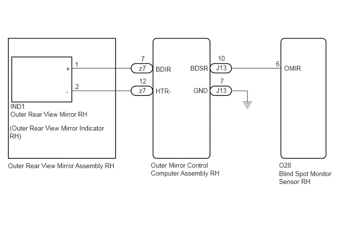
CAUTION / NOTICE / HINT
- NOTICE:
-
When checking for DTCs, make sure that the blind spot monitor main switch (warning canceling switch assembly) is on.
PROCEDURE
Clear the DTCs.
Click hereAudio / Visual / Telematics>PARK ASSIST / MONITORING>BLIND SPOT MONITOR SYSTEM>DTC CHECK / CLEAR
- Body Electrical > Blind Spot Monitor Master > Clear DTCs
- 50002 313
Recheck for DTCs and check if the same DTC is output again.
- Body Electrical > Blind Spot Monitor Master > Trouble Codes
- 50001 313
- OK:
No DTCs are output.
- Result:
Proceed to OK NG
OK
Click hereGeneral>INTRODUCTION>HOW TO TROUBLESHOOT ECU CONTROLLED SYSTEMS>HOW TO PROCEED WITH TROUBLESHOOTING
NG
Disconnect connector O28 from the blind spot monitor sensor RH.
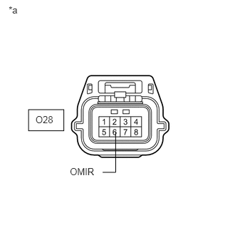
| *a | Front view of wire harness connector
(to Blind Spot Monitor Sensor RH) |
Measure the voltage according to the value(s) in the table below.
- Standard Voltage:
Tester Connection Condition Specified Condition O28-6 (OMIR) - Body ground Engine switch on (IG) Below 1 V
- Result:
Proceed to OK NG
OK
NG
Disconnect connector IND1 from the outer rear view mirror RH.
Measure the voltage according to the value(s) in the table below.
- Standard Voltage:
Tester Connection Condition Specified Condition O28-6 (OMIR) - Body ground Engine switch on (IG) Below 1 V
- Result:
Proceed to OK NG
OK
NG
Disconnect connector z7 from the outer mirror control computer assembly RH.
Measure the voltage according to the value(s) in the table below.
- Standard Voltage:
Tester Connection Condition Specified Condition O28-6 (OMIR) - Body ground Engine switch on (IG) Below 1 V
- Result:
Proceed to OK NG
OK
NG
Disconnect connector J13 from the outer mirror control computer assembly RH.
Measure the voltage according to the value(s) in the table below.
- Standard Voltage:
Tester Connection Condition Specified Condition O28-6 (OMIR) - Body ground Engine switch on (IG) Below 1 V
- Result:
Proceed to OK NG
OK
NG