RM19V0EQ
_59
Vehicle Exterior
_014620
WIPER / WASHER
_0074239
WIPER AND WASHER SYSTEM
J
WIPER / WASHER WIPER AND WASHER SYSTEM Rain Sensor Circuit
DESCRIPTION
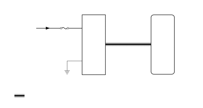
The windshield wiper relay assembly receives a signal from the rain sensor to control the auto wiper system.
WIRING DIAGRAM
4.934,2.582 5.373,2.759
0.439,0.177
10
I72
4.934,2.754 7.072,2.94
2.138,0.186
10
Windshield Wiper Relay Assembly
2.881,2.63 3.246,2.806
0.365,0.177
10
S1
2.881,2.801 3.706,2.988
0.825,0.186
10
Rain Sensor
3.789,1.317 3.992,1.484
0.203,0.167
10
1
2.97,2.034 3.22,2.201
0.25,0.167
10
ES
3.368,1.442 3.691,1.609
0.323,0.167
10
MPX
2.957,0.877 3.256,1.044
0.299,0.167
10
SIG
0.278,0.857 1.285,1.219
1.007,0.361
10
from IG1 NO. 2 Relay
1.762,1.016 2.8,1.201
1.038,0.186
10
ECU-IG1 NO. 2
5.411,1.442 5.895,1.609
0.484,0.167
10
MPX1
5.143,1.317 5.346,1.484
0.203,0.167
10
14
2.774,0.78 2.905,0.947
0.131,0.167
10
4
2.774,1.933 2.905,2.1
0.131,0.167
10
2
0.892,3.261 2.516,3.448
1.624,0.186
10
: Lin Communication Line
PROCEDURE
1.CHECK HARNESS AND CONNECTOR (WINDSHIELD WIPER RELAY ASSEMBLY - RAIN SENSOR)
a.
Disconnect the I72 windshield wiper relay assembly connector.
b.
Disconnect the S1 rain sensor connector.
c.
Measure the resistance according to the value(s) in the table below.
- Standard Resistance:
Tester Connection Condition Specified Condition I72-14 (MPX1) - S1-1 (MPX) Always Below 1 Ω S1-1 (MPX) - Body ground Always 10 kΩ or higher
- Result:
Proceed to OK NG
OK
2.CHECK HARNESS AND CONNECTOR (RAIN SENSOR - BATTERY AND BODY GROUND)
NG
REPAIR OR REPLACE HARNESS OR CONNECTOR
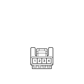
2.CHECK HARNESS AND CONNECTOR (RAIN SENSOR - BATTERY AND BODY GROUND)
a.
1.531,1.438 1.917,1.708
0.385,0.271
2.042,2.458 2.563,1.906
false
1.552,2.406 1.073,1.865
false
1.646,1.49 1.938,1.656
0.292,0.167
10
false
S1
0.896,1.667 1.344,1.958
0.448,0.292
10
false
ES
2.458,1.719 3,2.115
0.542,0.396
10
false
SIG
0.375,0.344 0.74,0.604
0.365,0.26
10
false
*a
| *a | Component with harness connected
(Rain Sensor) |
Measure the voltage according to the value(s) in the table below.
- Standard Voltage:
Tester Connection Condition Specified Condition S1-4 (SIG) - S1-2 (ES) Ignition switch ON 11 to 14 V
b.
Measure the resistance according to the value(s) in the table below.
- Standard Resistance:
Tester Connection Condition Specified Condition S1-2 (ES) - Body ground Always Below 1 Ω
- Result:
Proceed to OK NG
OK
3.INSPECT RAIN SENSOR
NG
REPAIR OR REPLACE HARNESS OR CONNECTOR
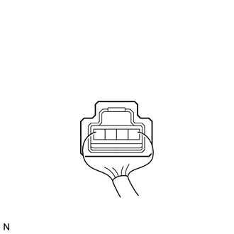
3.INSPECT RAIN SENSOR
a.
0.563,1.615 0.969,1.875
0.406,0.26
1.979,1.979 2.292,1.563
false
1.688,1.417 1.813,1.979
false
0.313,0.229 0.74,0.708
0.427,0.479
10
false
*a
2.198,1.375 2.635,1.531
0.438,0.156
10
false
MPX
1.542,1.229 1.813,1.385
0.271,0.156
10
false
ES
0.698,1.656 1,1.938
0.302,0.281
10
false
S1
| *a | Component with harness connected
(Rain Sensor) |
Reconnect the S1 rain sensor connector.
b.
Connect an oscilloscope to the rain sensor connector.
c.
Check for pulses.
- OK:
Tester Connection Condition Specified Condition S1-1 (MPX) - S1-2 (ES) Ignition switch ON Pulse generation
- Result:
Proceed to OK NG
OK
PROCEED TO NEXT SUSPECTED AREA SHOWN IN PROBLEM SYMPTOMS TABLE
NG