CRUISE CONTROL CRUISE CONTROL SYSTEM Clutch Switch Circuit
DESCRIPTION
Clutch switch circuit inspection is necessary for manual transaxle vehicles.
When the clutch pedal is released, the ECM receives battery voltage through the ECU-IG1 No. 1 fuse.
When the clutch pedal is depressed, this interrupts the battery voltage being sent to terminal D of the ECM. The ECM cancels control of vehicle speed by the cruise control system when the battery voltage is no longer received by terminal D of the ECM.
WIRING DIAGRAM
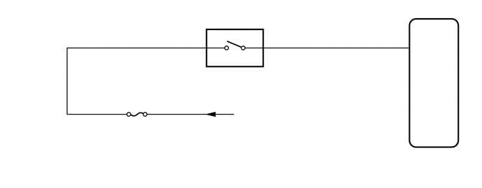
CAUTION / NOTICE / HINT
- NOTICE:
-
Inspect the fuses for circuits related to this system before performing the following procedure.
PROCEDURE
Disconnect the ECM connector.
Measure the voltage according to the value(s) in the table below.
- Standard Voltage:
Tester Connection Condition Specified Condition E26-67 (D) - Body ground Clutch pedal depressed Below 1 V Clutch pedal released 11 to 14 V
- Result:
Proceed to OK NG
OK
NG
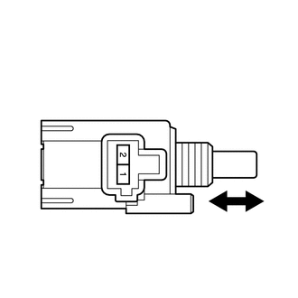
| *a | Component without harness connected
(Clutch Switch Assembly) |
| *b | Pushed in |
| *c | Free |
Remove the clutch switch assembly.
Click hereDrivetrain>CLUTCH>CLUTCH PEDAL>REMOVAL
Measure the resistance according to the value(s) in the table below.
- Standard Resistance (Check for Open):
Tester Connection Switch Condition Specified Condition 1 (CL+) - 2 (CL-) Switch pin pushed in Below 1 Ω
- Standard Resistance (Check for Short):
Tester Connection Switch Condition Specified Condition 1 (CL+) - 2 (CL-) Switch pin free 10 kΩ or higher
- Result:
Proceed to OK NG
OK
NG
Click hereDrivetrain>CLUTCH>CLUTCH PEDAL>REMOVAL
Disconnect the ECM connector.
Disconnect the clutch switch assembly connector.
Measure the resistance according to the value(s) in the table below.
- Standard Resistance (Check for Open):
Tester Connection Condition Specified Condition E26-67 (D) - Body ground Always Below 1 Ω
- Standard Resistance (Check for Short):
Tester Connection Condition Specified Condition E26-67 (D) - Body ground Always 10 kΩ or higher
- Result:
Proceed to OK NG
OK
NG