NAVIGATION / MULTI INFO DISPLAY NAVIGATION SYSTEM(for SD) B1324 Lost Communication with Meter
DESCRIPTION
This DTC is stored when a communication error occurs between the navigation receiver assembly and combination meter assembly.
| DTC No. | Detection Item | DTC Detection Condition | Trouble Area |
|---|---|---|---|
| B1324 | Lost Communication with Meter | After the navigation receiver assembly receives a registration information signal, which is sent by the combination meter assembly when the ignition switch is turned to ACC, 1 or more times, the navigation receiver assembly cannot receive the signal for 30 seconds or more. | ·
Combination meter assembly ·
Navigation receiver assembly ·
Harness or connector |
WIRING DIAGRAM
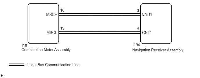
PROCEDURE
Check if meter / gauge system DTCs are output.
Click hereVehicle Interior>METER / GAUGE / DISPLAY>METER / GAUGE SYSTEM>DTC CHECK / CLEAR
- Body Electrical > Combination Meter > Trouble Codes
- 50001 122
- Result:
Result Proceed to DTCs are not output. A DTCs are output. B
A
B
Click hereVehicle Interior>METER / GAUGE / DISPLAY>METER / GAUGE SYSTEM>HOW TO PROCEED WITH TROUBLESHOOTING
Disconnect the I194 navigation receiver assembly connector.
Disconnect the I18 combination meter assembly connector.
Measure the resistance according to the value(s) in the table below.
- Standard Resistance:
Tester Connection Condition Specified Condition I194-3 (CNH1) - I18-18 (MSCH) Always Below 1 Ω I194-4 (CNL1) - I18-19 (MSCL) Always Below 1 Ω I194-3 (CNH1) - Body ground Always 10 kΩ or higher I194-4 (CNL1) - Body ground Always 10 kΩ or higher
- Result:
Proceed to OK NG
OK
NG
Replace the combination meter assembly with a new or known good one.
Click hereVehicle Interior>METER / GAUGE / DISPLAY>COMBINATION METER>REMOVAL
Clear the DTCs.
- Body Electrical > Navigation System > Clear DTCs
- 50002 212
Recheck for DTCs and check that no DTCs are output.
- Body Electrical > Navigation System > Trouble Codes
- 50001 212
- OK:
No DTCs are output.
- Result:
Proceed to OK NG
OK
NG
Click hereAudio / Visual / Telematics>NAVIGATION / MULTI INFO DISPLAY>NAVIGATION RECEIVER(for SD)>REMOVAL