Home › Drivetrain ยท U241E AUTOMATIC TRANSMISSION / TRANSAXLE › SPEED SENSOR

SPEED SENSOR > INSTALLATION

for Preparation Click here


1. INSTALL SPEED SENSOR NC
  1. Coat a new O-ring with ATF and install it to the speed sensor NC.

  1. Install the speed sensor NC to the automatic transaxle assembly with a new bolt.

    Torque:
    8.8 N*m{ 90 kgf*cm , 78 in.*lbf }

  1. Connect the connector to the speed sensor NC.


2. INSTALL SPEED SENSOR NT
  1. Coat a new O-ring with ATF and install it to the speed sensor NT.

  1. Install the speed sensor NT to the automatic transaxle assembly with the bolt.

    Torque:
    Precoated Bolt:
    8.8 N*m{ 90 kgf*cm , 78 in.*lbf }
    Uncoated Bolt:
    11 N*m{ 115 kgf*cm , 8 ft.*lbf }

    NOTICE:
    If a precoated bolt has been used, replace it with a new one.

  1. Connect the connector to the speed sensor NT.

  1. Install the wire harness clamp bracket to the body with the bolt.

    Torque:
    8.0 N*m{ 82 kgf*cm , 71 in.*lbf }

  1. Connect the wire harness clamp to the wire harness clamp bracket.


3. INSTALL BATTERY TRAY
  1. Install the battery tray to the body.


4. INSTALL BATTERY
  1. Install the battery to the battery tray.

  1. Install the battery clamp with the bolt and nut.

    Torque:
    Bolt:
    9.0 N*m{ 92 kgf*cm , 80 in.*lbf }
    Nut:
    3.5 N*m{ 36 kgf*cm , 31 in.*lbf }

  1. Connect the cable to the positive (+) battery terminal.

    Torque:
    6.0 N*m{ 61 kgf*cm , 53 in.*lbf }


5. INSTALL AIR CLEANER CASE SUB-ASSEMBLY
  1. Install the air cleaner case sub-assembly with the 3 bolts.

    Torque:
    5.0 N*m{ 51 kgf*cm , 44 in.*lbf }

  1. Connect the wire harness clamp.


6. INSTALL AIR CLEANER CAP SUB-ASSEMBLY
  1. Install the air cleaner filter element to the air cleaner case sub-assembly.


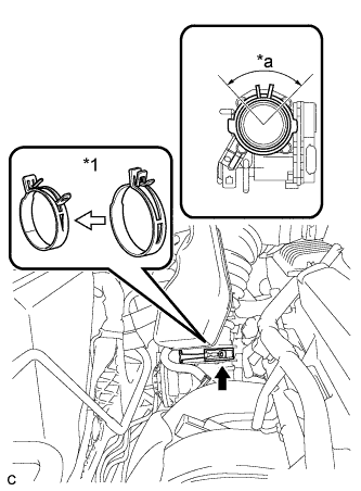
    A265342E01
  1. Connect the air cleaner cap sub-assembly to the throttle with motor body assembly and release the lock of the air cleaner hose clamp.
    Text in Illustration 
    *1
    Air Cleaner Hose Clamp

    NOTICE:
    1. Align the groove of the air cleaner cap sub-assembly with the tab of the throttle with motor body assembly and install the hose.
    2. Make sure that the tab of the air cleaner hose clamp stays within the range shown by *a.

  1. Connect the ventilation hose to the cylinder head cover.

  1. Install the air cleaner cap sub-assembly and tighten the 2 bolts.

    Torque:
    5.0 N*m{ 51 kgf*cm , 44 in.*lbf }

  1. Connect the wire harness clamp.

  1. Connect the mass air flow meter connector.

  1. Connect the purge line hose to the 2 clamps.

  1. Connect the 2 vacuum switching valve vacuum hoses.

  1. Connect the vacuum switching valve connector.


7. INSTALL INLET AIR CLEANER ASSEMBLY
  1. Install the inlet air cleaner assembly with the 2 bolts.

    Torque:
    8.0 N*m{ 82 kgf*cm , 71 in.*lbf }


8. INSTALL COOL AIR INTAKE DUCT SEAL
  1. Install the cool air intake duct seal with the 9 clips.


9. INSTALL NO. 1 ENGINE COVER SUB-ASSEMBLY
  1. Install the No. 1 engine cover sub-assembly with the 2 nuts.

    Torque:
    9.0 N*m{ 92 kgf*cm , 80 in.*lbf }


10. CONNECT CABLE TO NEGATIVE BATTERY TERMINAL

NOTICE:
When disconnecting the cable, some systems need to be initialized after the cable is reconnected (Click here).