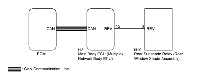
REAR SUNSHADE SYSTEM > Rear Sunshade Shift-linked Function does not Operate when Shift Lever is Moved to R Position |
| 1.READ VALUE USING INTELLIGENT TESTER |
Connect the intelligent tester to the DLC3.
Turn the engine switch on (IG).
Turn the intelligent tester on.
Enter the following menus: Powertrain / Engine / Data List.
Read the Data List according to the display on the intelligent tester.
| Tester Display | Measurement Item/Range | Normal Condition | Diagnostic Note |
| Shift SW Status (R Range) | PNP switch status / ON or OFF | ON: Shift lever in R OFF: Shift lever not in R | When the shift lever position displayed on the intelligent tester differs from the actual position, adjustment of the PNP switch or the shift cable may be incorrect. |
|
| ||||
| OK | |
 |
| 2.CHECK ECM (REVERSE SIGNAL) |
Check if the shift position indicator in the combination meter assembly operates normally.
|
| ||||
| OK | |
|
| 3.PERFORM ACTIVE TEST USING INTELLIGENT TESTER |
Connect the intelligent tester to the DLC3.
Turn the engine switch on (IG).
Turn the intelligent tester on.
Enter the following menus: Body / Main Body / Active Test.
Perform the Active Test according to the display on the intelligent tester.
| Tester Display | Test Part | Control Range | Diagnostic Note |
| Reverse Gear Signal | Reverse signal | OFF/ON | - |
|
| ||||
| OK | ||
 | ||
| ||
| 4.CHECK HARNESS AND CONNECTOR (REVERSE SIGNAL) |
Disconnect the N19 rear sunshade relay (rear window shade assembly) connector.
Measure the voltage according to the value(s) in the table below.
| Tester Connection | Condition | Specified Condition |
| N19-3 (REV) - Body ground | Always | 11 to 14 V |
|
| ||||
| OK | ||
| ||
| ||
| 5.CHECK HARNESS AND CONNECTOR (REAR SUNSHADE RELAY (REAR WINDOW SHADE ASSEMBLY) - MAIN BODY ECU (MULTIPLEX NETWORK BODY ECU)) |
Disconnect the I13 main body ECU (multiplex network body ECU) connectors.
Measure the resistance according to the value(s) in the table below.
| Tester Connection | Condition | Specified Condition |
| N19-3 (REV) - I13-15 (REV) | Always | Below 1 Ω |
| I13-15 (REV) - Body ground | Always | 10 kΩ or higher |
|
| ||||
| OK | ||
| ||
| ||

