
SMART ENTRY AND START SYSTEM (for Start Function) > Engine does not Start |
| Problem Symptom | Data List Item | Active Test Item |
| Engine does not start | Power Source Control
Entry & Start
Starting Control
| - |
| 1.CHECK BATTERY |
Measure the battery voltage.
| OK | |
|
| 2.CHECK FOR DTC (ALL) |
Using the intelligent tester, confirm the output of DTCs for all systems.
|
| ||||
| OK | |
|
| 3.CHECK WAVE ENVIRONMENT |
If the problem occurs in certain locations or times of day, the possibility of wave interference is high.
| NEXT | |
|
| 4.CHECK ENGINE SWITCH CONDITION |
Get into the vehicle while carrying an electrical key transmitter sub-assembly.
Move the shift lever to P.
With the brake pedal released, check that pressing the engine switch causes the power source mode to change.
| Result | Proceed to |
| Off → on (ACC) → on (IG) → off | A |
| Power source mode does not change to on (ACC) and on (IG) | B |
| Power source mode changes to on (IG) but not to on (ACC) | C |
| Power source mode changes to on (ACC) but not to on (IG) | D |
|
| ||||
|
| ||||
|
| ||||
| A | |
|
| 5.CHECK CRANKING FUNCTION |
Get into the vehicle while carrying an electrical key transmitter sub-assembly.
Move the shift lever to P.
Depress the brake pedal.
w/o Multi-information Display:
Confirm that the smart key warning light is illuminated in green, and then press the engine switch and check that the engine cranks.
w/ Multi-information Display:
Confirm that the smart warning light is displayed , and then press the engine switch and check that the engine cranks.
| Result | Proceed to |
| OK | A |
| NG (for 2AR-FE) | B |
| NG (for 2GR-FE) | C |
|
| ||||
|
| ||||
| A | |
|
| 6.CHECK SECURITY INDICATOR LIGHT (ENGINE IMMOBILISER SYSTEM UNSET) |
Get into the vehicle while carrying an electrical key transmitter sub-assembly.
Move the shift lever to P.
Press the engine switch with the brake pedal released and check that the security indicator light changes from blinking to off at the same time that the power source mode changes to on (ACC).
| Result | Proceed to |
| OK | A |
| NG (w/ wireless door lock buzzer answer back function) | B |
| NG (w/o wireless door lock buzzer answer back function) | C |
|
| ||||
|
| ||||
| A | |
|
| 7.CHECK COMBINATION METER ASSEMBLY |
Get into the vehicle while carrying the key, move the shift lever to P, press the engine switch while depressing the brake pedal and check that the combination meter indicator changes.
|
| ||||
| OK | |
|
| 8.READ VALUE USING INTELLIGENT TESTER (STARTER SW) |
Connect the intelligent tester to the DLC3.
Turn the engine switch on (IG).
Turn the intelligent tester on.
Enter the following menus: Body / Starting Control / Data List.
Get into the vehicle while carrying an electrical key transmitter sub-assembly and press the engine switch with the shift lever Fin P and brake pedal depressed to check if the Data List display changes.
| Tester Display | Measurement Item/Range | Normal Condition | Diagnostic Note |
| Starter SW | Starter operation request/ON or OFF | ON: Starter operation requested OFF: Starter operation not requested | When malfunctioning, the engine will not crank. |
|
| ||||
| OK | |
|
| 9.INSPECT ST RELAY |
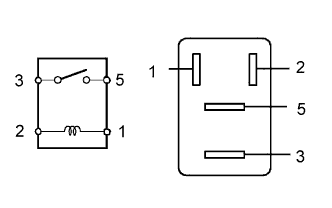 |
Remove the ST relay from the engine room relay block and junction block assembly.
Measure the resistance according to the value(s) in the table below.
| Tester Connection | Condition | Specified Condition |
| 1 - 2 | 20°C (68°F) | 93.8 to 136.4 Ω |
| 3 - 5 | Battery voltage not applied to terminals 1 and 2 | 10 kΩ or higher |
| Battery voltage applied to terminals 1 and 2 | Below 1 Ω |
Reinstall the ST relay to the engine room relay block and junction block assembly.
|
| ||||
| OK | |
|
| 10.CHECK HARNESS AND CONNECTOR (CERTIFICATION ECU (SMART KEY ECU ASSEMBLY) - BODY GROUND) |
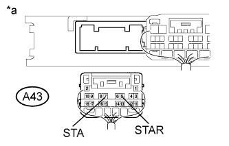 |
Disconnect the A43 connector from the certification ECU (smart key ECU assembly).
Move the shift lever to P or N.
Measure the resistance according to the value(s) in the table below.
| Tester Connection | Condition | Specified Condition |
| A43-5 (STAR) - Body ground | 20°C (68°F) | 93.75 to 136.36 Ω |
| A43-7 (STA) - Body ground |
| *a | Rear view of wire harness connector (to Certification ECU (Smart Key ECU Assembly)) |
|
| ||||
| OK | |
|
| 11.INSPECT STARTER ASSEMBLY |
Inspect the starter assembly (for 2AR-FE, 1.6 kW Type) (Click here).
Inspect the starter assembly (for 2AR-FE, 1.7 kW Type) (Click here).
Inspect the starter assembly (for 2GR-FE) (Click here).
| Result | Proceed to |
| OK | A |
| NG (for 2AR-FE, 1.6 kW Type) | B |
| NG (for 2AR-FE, 1.6 kW Type) | C |
| NG (for 2GR-FE) | D |
|
| ||||
|
| ||||
|
| ||||
| A | |
|
| 12.CHECK HARNESS AND CONNECTOR (BATTERY - STARTER AND ENGINE ROOM RELAY BLOCK AND JUNCTION BLOCK ASSEMBLY) |
Remove the starter assembly from the vehicle to perform an inspection.
Remove the ST relay from the engine room relay block and junction block assembly.
Measure the voltage according to the value(s) in the table below.
| Tester Connection | Condition | Specified Condition |
| F2-1 (B) - Body ground | Always | 11 to 14 V |
| 5 - Body ground | Always | 11 to 14 V |
Measure the resistance according to the value(s) in the table below.
| Tester Connection | Condition | Specified Condition |
| 3 - E9-1 (ST) | Always | Below 1 Ω |
| 3 or E9-1 (ST) - Body ground | Always | 10 kΩ or higher |
|
| ||||
| OK | ||
 | ||
| ||
| 13.READ VALUE USING INTELLIGENT TESTER (S CODE CHECK) |
Connect the intelligent tester to the DLC3.
Turn the engine switch on (IG).
Turn the intelligent tester on.
Enter the following menus: Body / Power Source Control / Data List.
According to the display on the intelligent tester, read the Data List.
| Tester Display | Measurement Item/Range | Normal Condition | Diagnostic Note |
| S Code Check | Verification result between certification ECU (smart key ECU assembly) and ID code box (immobiliser code ECU)/OK or NG | OK: Verification result normal NG: Verification result abnormal | When NG is displayed:
|
|
| ||||
| OK | |
|
| 14.CHECK STEERING LOCK |
Check that the steering unlocks when the engine switch is turned on (ACC).
|
| ||||
| OK | |
|
| 15.READ VALUE USING INTELLIGENT TESTER (IMMOBILISER) |
Connect the intelligent tester to the DLC3.
Turn the engine switch on (IG).
Turn the intelligent tester on.
Enter the following menus: Body / Entry & Start / Data List.
According to the display on the intelligent tester, read the Data List.
| Tester Display | Measurement Item/Range | Normal Condition | Diagnostic Note |
| Immobiliser | Engine immobiliser system determined by certification ECU (smart key ECU assembly)/ Set or Unset | Set: Engine immobiliser system set (engine start prohibited) (engine switch off) Unset: Engine immobiliser system unset (engine start permitted) (engine switch on (ACC) or on (IG)) | The engine cannot be started when Set is displayed.
|
| Result | Proceed to |
| OK | A |
| NG (w/ wireless door lock buzzer answer back function) | B |
| NG (w/o wireless door lock buzzer answer back function) | C |
|
| ||||
|
| ||||
| A | |
|
| 16.READ VALUE USING INTELLIGENT TESTER (STARTER REQUEST SIGNAL) |
Connect the intelligent tester to the DLC3.
Turn the engine switch on (IG).
Turn the intelligent tester on.
Enter the following menus: Body / Power Source Control / Data List.
According to the display on the intelligent tester, read the Data List.
| Tester Display | Measurement Item/Range | Normal Condition | Diagnostic Note |
| Starter Request Signal | Engine start request signal status/ON or OFF | ON: With the shift lever in P and brake pedal depressed, the engine switch is pressed and held OFF: After approx. 1 sec. has elapsed, the engine switch is released |
|
| Result | Proceed to |
| OK | A |
| NG (w/ wireless door lock buzzer answer back function) | B |
| NG (w/o wireless door lock buzzer answer back function) | C |
|
| ||||
|
| ||||
| A | ||
| ||
| ||
| 17.READ VALUE USING INTELLIGENT TESTER (NEUTRAL SW/ CLUTCH SW, SHIFT POSITION P OR N) |
Connect the intelligent tester to the DLC3.
Turn the engine switch on (IG).
Turn the intelligent tester on.
Enter the following menus: Body / Power Source Control or Starting Control / Data List.
According to the display on the intelligent tester, read the Data List.
| Tester Display | Measurement Item/Range | Normal Condition | Diagnostic Note |
| Neutral SW/ Clutch SW | Shift position (P and N)/ON or OFF | ON: Shift lever in P or N OFF: Shift lever in any position other than P or N |
|
| Tester Display | Measurement Item/Range | Normal Condition | Diagnostic Note |
| Shift Position P or N | Park/neutral position switch status/ON or OFF | ON: Shift lever in P or N OFF: Shift lever in any position other than P or N | When malfunctioning, the engine will not crank. |
|
| ||||
| OK | |
|
| 18.READ VALUE USING INTELLIGENT TESTER (STOP LIGHT SWITCH1) |
Connect the intelligent tester to the DLC3.
Turn the engine switch on (IG).
Turn the intelligent tester on.
Enter the following menus: Body / Power Source Control / Data List.
According to the display on the intelligent tester, read the Data List.
| Tester Display | Measurement Item/Range | Normal Condition | Diagnostic Note |
| Stop Light Switch1 | State of brake pedal/ON or OFF | ON: Brake pedal depressed OFF: Brake pedal released |
|
|
| ||||
| OK | ||
| ||
| ||
| 19.CHECK PARK/NEUTRAL POSITION SWITCH ASSEMBLY |
Disconnect the E4 park/neutral position switch assembly connector.
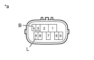 |
Measure the resistance according to the value(s) in the table below.
| Tester Connection | Condition | Specified Condition |
| 4 (B) - 9 (L) | Shift lever in P or N | Below 1 Ω |
| Shift lever in any position other than P or N | 10 kΩ or higher |
| *a | Component without harness connected (Park/Neutral Position Switch Assembly) |
| Result | Proceed to |
| OK | A |
| NG (for U660E) | B |
| NG (for U760E) | C |
|
| ||||
|
| ||||
| A | |
|
| 20.CHECK HARNESS AND CONNECTOR (CERTIFICATION ECU (SMART KEY ECU ASSEMBLY) - PARK/NEUTRAL POSITION SWITCH) |
Disconnect the A43 connector from the certification ECU (smart key ECU assembly).
Disconnect the E4 connector from the park/neutral position switch.
Measure the resistance according to the value(s) in the table below.
| Tester Connection | Condition | Specified Condition |
| A43-5 (STAR) - E4-4 (B) | Always | Below 1 Ω |
| A43-5 (STAR) or E4-4 (B) - Body ground | Always | 10 kΩ or higher |
Reconnect the park/neutral position switch connector.
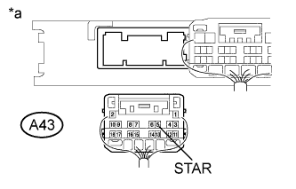 |
Measure the voltage according to the value(s) in the table below.
| Tester Connection | Condition | Specified Condition |
| A43-5 (STAR) - Body ground | Engine switch pressed and held with brake pedal depressed (starter on) → Engine switch released after approximately 1 second elapses (starter off) | 6 V or higher* → 1.5 V or less |
| *a | Rear view of wire harness connector (to Certification ECU (Smart Key ECU Assembly)) |
|
| ||||
| OK | ||
| ||
| ||
| 21.INSPECT STOP LIGHT SWITCH ASSEMBLY |
Disconnect the A33 connector from the stop light switch assembly.
Inspect the stop light switch assembly (Click here).
|
| ||||
| OK | |
|
| 22.CHECK HARNESS AND CONNECTOR (CERTIFICATION ECU (SMART KEY ECU ASSEMBLY) - STOP LIGHT SWITCH ASSEMBLY) |
Disconnect the A33 connector from the stop light switch assembly.
Measure the resistance according to the value(s) in the table below.
| Tester Connection | Condition | Specified Condition |
| A43-18 (STP1) - A33-1 | Always | Below 1 Ω |
| A43-18 (STP1) or A33-1 - Body ground | Always | 10 kΩ or higher |
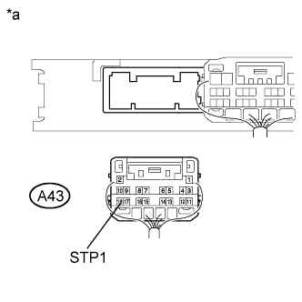 |
Reconnect the A43 stop light switch assembly connector.
Measure the voltage according to the value(s) in the table below.
| Tester Connection | Condition | Specified Condition |
| A43-18 (STP1) - Body ground | Brake pedal released | 1 V or less |
| Brake pedal depressed | 9 V or higher |
| *a | Rear view of wire harness connector (Certification ECU (Smart Key ECU Assembly)) |
|
| ||||
| OK | ||
| ||
| ||
| 23.READ VALUE USING INTELLIGENT TESTER (STEERING UNLOCK SWITCH) |
Connect the intelligent tester to the DLC3.
Turn the engine switch on (IG).
Turn the intelligent tester on.
Enter the following menus: Body / Power Source Control / Data List.
According to the display on the intelligent tester, read the Data List.
| Tester Display | Measurement Item/Range | Normal Condition | Diagnostic Note |
| Steering Unlock Switch | State of steering unlock sensor signal output from steering lock actuator assembly/ON or OFF | ON: Steering unlocked OFF: Steering locked |
|
|
| ||||
| OK | ||
| ||
| ||
| 24.READ VALUE USING INTELLIGENT TESTER (L CODE CHECK) |
Connect the intelligent tester to the DLC3.
Turn the engine switch on (IG).
Turn the intelligent tester on.
Enter the following menus: Body / Entry & Start / Data List.
According to the display on the intelligent tester, read the Data List.
| Tester Display | Measurement Item/Range | Normal Condition | Diagnostic Note |
| L Code Check | w/ wireless door lock buzzer answer back function: Verification result between certification ECU (smart key ECU assembly) and steering lock ECU (steering lock actuator assembly)/OK or NG w/o wireless door lock buzzer answer back function: Verification result between ID code box (immobiliser code ECU) and steering lock ECU (steering lock actuator assembly)/OK or NG | OK: Verification result normal NG: Verification result abnormal |
|
|
| ||||
| OK | |
|
| 25.REPLACE STEERING LOCK ECU (STEERING LOCK ACTUATOR ASSEMBLY) |
Replace the steering lock ECU (steering lock actuator assembly) with a new one .
Perform the registration procedures (Refer to the Service Bulletin).
Turn the engine switch on (IG).
Operate the steering wheel and check the steering condition.
| NEXT | ||
| ||
| ||
| 26.REPLACE STEERING LOCK ECU (STEERING LOCK ACTUATOR ASSEMBLY) |
Replace the steering lock ECU (steering lock actuator assembly) with a new one .
Perform the registration procedures (Refer to the Service Bulletin).
Use the Data List to check if L code certification is functioning properly again.
| Tester Display | Measurement Item/Range | Normal Condition | Diagnostic Note |
| L Code Check | w/ wireless door lock buzzer answer back function: Verification result between certification ECU (smart key ECU assembly) and steering lock ECU (steering lock actuator assembly)/OK or NG w/o wireless door lock buzzer answer back function: Verification result between ID code box (immobiliser code ECU) and steering lock ECU (steering lock actuator assembly)/OK or NG | OK: Verification result normal NG: Verification result abnormal |
|
| Result | Proceed to |
| OK | A |
| NG (w/ wireless door lock buzzer answer back function) | B |
| NG (w/o wireless door lock buzzer answer back function) | C |
|
| ||||
|
| ||||
| A | ||
| ||
| ||
| 27.REPLACE CERTIFICATION ECU (SMART KEY ECU ASSEMBLY) |
Replace the certification ECU (smart key ECU assembly) with a new one (Refer to the Service Bulletin).
Perform the registration procedures (Refer to the Service Bulletin).
Use the Data List to check if S code certification (smart key ECU assembly) is functioning properly again.
| Tester Display | Measurement Item/Range | Normal Condition | Diagnostic Note |
| S Code Check | Verification result between certification ECU (smart key ECU assembly) and ID code box (immobiliser code ECU)/OK or NG | OK: Verification result normal NG: Verification result abnormal | When NG is displayed:
|
|
| ||||
| OK | ||
| ||
| ||
| 28.REPLACE ID CODE BOX (IMMOBILISER CODE ECU) |
Replace the ID code box (immobiliser code ECU) with a new one (Refer to the Service Bulletin).
Perform the registration procedures (Refer to the Service Bulletin).
Use the Data List to check if S code certification is functioning properly again.
| Tester Display | Measurement Item/Range | Normal Condition | Diagnostic Note |
| S Code Check | Verification result between certification ECU (smart key ECU assembly) and ID code box (immobiliser code ECU)/OK or NG | OK: Verification result normal NG: Verification result abnormal | When NG is displayed:
|
| NEXT | ||
| ||
| ||

