Remove the radiator cap sub-assembly.
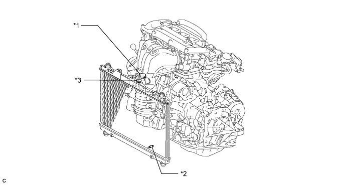
| *1 | Radiator Cap Sub-assembly | *2 | Radiator Drain Cock Plug |
| *3 | Cylinder Block Drain Cock Plug | - |
- HINT:
- Collect the engine coolant in a container and dispose of it according to the regulations in your area.
ENGINE ASSEMBLY > REMOVAL |
| 1. PRECAUTION |
| 2. RECOVER REFRIGERANT FROM AIR CONDITIONING SYSTEM |
Turn the A/C switch on.
Operate the air conditioning with a set temperature of 25°C (77°F) and the blower at low for 10 minutes to circulate the refrigerant. This causes most of the compressor oil from the various components of the air conditioning system to collect in the air conditioning compressor.
Turn the ignition switch off.
Recover the refrigerant from the air conditioning system using a refrigerant recovery unit.
| 3. DISCHARGE FUEL SYSTEM PRESSURE |
| 4. DISCONNECT CABLE FROM NEGATIVE BATTERY TERMINAL |
| 5. DRAIN ENGINE OIL |
Remove the oil filler cap.
Remove the oil pan drain plug and gasket, and drain the oil into a container.
Clean and install the oil pan drain plug with a new gasket.
| 6. DRAIN AUTOMATIC TRANSAXLE FLUID |
Using a 10 mm hexagon socket wrench, remove the drain plug and gasket, and drain the ATF.
Using a 10 mm hexagon socket wrench, install a new gasket and the drain plug.
| 7. DRAIN ENGINE COOLANT |
Loosen the radiator drain cock plug.
Loosen the cylinder block drain cock plug.
Remove the radiator cap sub-assembly.
| *1 | Radiator Cap Sub-assembly | *2 | Radiator Drain Cock Plug |
| *3 | Cylinder Block Drain Cock Plug | - |
| 8. REMOVE WINDSHIELD WIPER MOTOR AND LINK ASSEMBLY |
| 9. REMOVE FRONT OUTER COWL TOP PANEL SUB-ASSEMBLY |
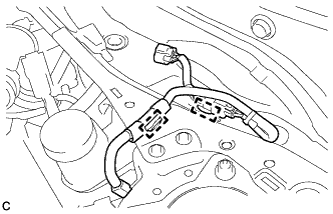 |
Disengage the 2 clamps and separate the wire harness from the front outer cowl top panel sub-assembly.
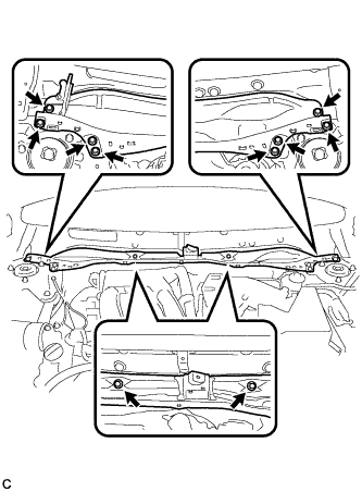 |
Remove the 10 bolts and front outer cowl top panel sub-assembly.
| 10. REMOVE COOL AIR INTAKE DUCT SEAL |
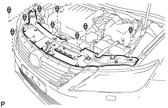 |
Remove the 9 clips and cool air intake duct seal.
| 11. REMOVE NO. 1 ENGINE COVER SUB-ASSEMBLY |
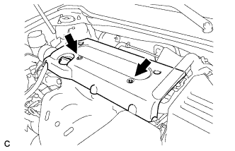 |
Remove the 2 nuts and No. 1 engine cover sub-assembly.
| 12. REMOVE INLET AIR CLEANER ASSEMBLY |
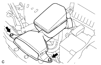 |
Remove the 2 bolts and inlet air cleaner assembly.
| 13. REMOVE AIR CLEANER CAP SUB-ASSEMBLY |
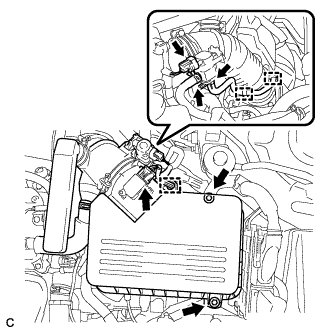 |
Disconnect the vacuum switching valve connector.
Disconnect the 2 vacuum switching valve vacuum hoses.
Disconnect the purge line hose from the 2 clamps.
Disconnect the mass air flow meter connector.
Disconnect the wire harness clamp.
Loosen the 2 bolts and separate the air cleaner cap sub-assembly.
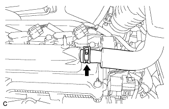 |
Disconnect the ventilation hose from the cylinder head cover sub-assembly.
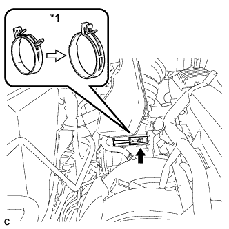 |
Lock the air cleaner hose clamp as shown in the illustration, and disconnect the air cleaner cap sub-assembly from the throttle with motor body assembly.
| *1 | Air Cleaner Hose Clamp |
Remove the air cleaner filter element from the air cleaner case sub-assembly.
| 14. REMOVE AIR CLEANER CASE SUB-ASSEMBLY |
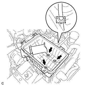 |
Disconnect the wire harness clamp.
Remove the 3 bolts and air cleaner case sub-assembly.
| 15. REMOVE NO. 2 ENGINE MOUNTING STAY RH |
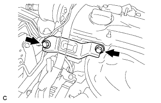 |
Remove the 2 bolts and No. 2 engine mounting stay RH.
| 16. REMOVE ENGINE MOVING CONTROL ROD SUB-ASSEMBLY |
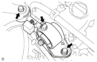 |
Remove the 3 bolts and engine moving control rod sub-assembly.
| 17. REMOVE NO. 2 ENGINE MOUNTING BRACKET RH |
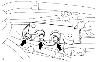 |
Remove the 3 bolts and No. 2 engine mounting bracket RH.
| 18. DISCONNECT UNION TO VACUUM TUBE HOSE |
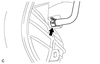 |
Disconnect the union to vacuum tube hose from the intake manifold.
| 19. DISCONNECT NO. 1 RADIATOR HOSE |
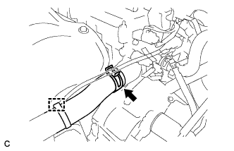 |
Disconnect the wire harness clamp and No. 1 radiator hose.
| 20. DISCONNECT NO. 2 RADIATOR HOSE |
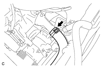 |
Disconnect the No. 2 radiator hose.
| 21. DISCONNECT INLET NO. 1 OIL COOLER HOSE |
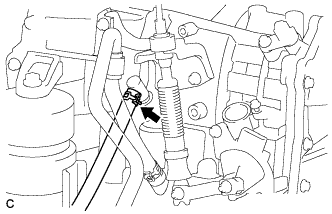 |
Disconnect the inlet No. 1 oil cooler hose from the automatic transaxle assembly.
| 22. DISCONNECT OUTLET NO. 1 OIL COOLER HOSE |
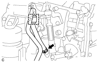 |
Disconnect the hose clamp and outlet No. 1 oil cooler hose from the automatic transaxle assembly.
| 23. DISCONNECT INLET HEATER WATER HOSE |
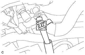 |
Disconnect the breather hose.
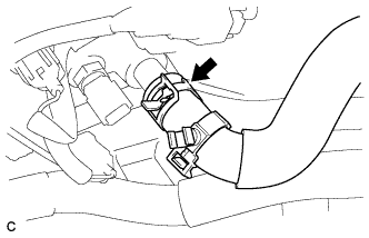 |
Disconnect the inlet heater water hose.
| 24. DISCONNECT OUTLET HEATER WATER HOSE |
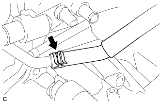 |
Disconnect the outlet heater water hose.
| 25. REMOVE STARTER ASSEMBLY |
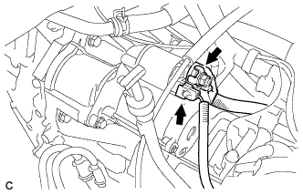 |
Disconnect the connector.
Open the terminal cap, remove the nut and disconnect the starter wire.
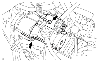 |
Remove the 2 bolts and starter assembly.
| 26. DISCONNECT ENGINE WIRE |
Remove the No. 1 relay block cover.
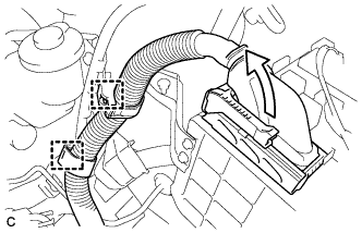 |
Pull up the lever and disconnect the ECM connector and 2 wire harness clamps.
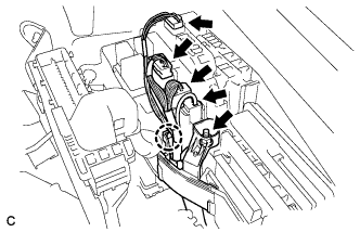 |
Disconnect the 4 connectors and remove the nut.
Using a screwdriver, disengage the claw and separate the engine wire.
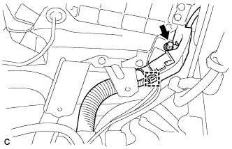 |
Remove the bolt and disconnect the wire harness clamp.
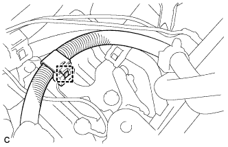 |
Disconnect the wire harness clamp.
| 27. DISCONNECT TRANSMISSION CONTROL CABLE ASSEMBLY |
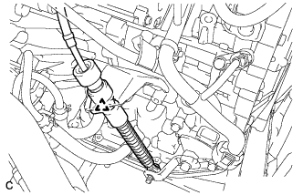
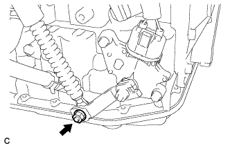 |
Remove the nut and disconnect the transmission control cable assembly from the control shaft lever.
 |
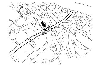
Remove the clip and disconnect the transmission control cable assembly from the control cable bracket.
 |
Disconnect the control cable from the control cable support.
| 28. DISCONNECT NO. 1 COOLER REFRIGERANT DISCHARGE HOSE |
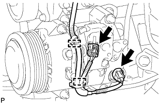 |
Disconnect the 2 connectors.
Disengage the 2 clamps.
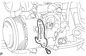 |
Remove the bolt and bracket.
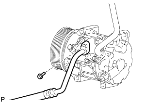 |
Remove the bolt and disconnect the No. 1 cooler refrigerant discharge hose from the compressor assembly with pulley.
Remove the O-ring from the No. 1 cooler refrigerant discharge hose.
| 29. DISCONNECT NO. 1 COOLER REFRIGERANT SUCTION HOSE |
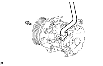 |
Remove the bolt and disconnect the No. 1 cooler refrigerant suction hose from the compressor assembly with pulley.
Remove the O-ring from the No. 1 cooler refrigerant suction hose.
| 30. DISCONNECT FUEL TUBE SUB-ASSEMBLY |
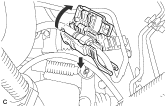 |
Remove the No. 1 fuel pipe clamp.
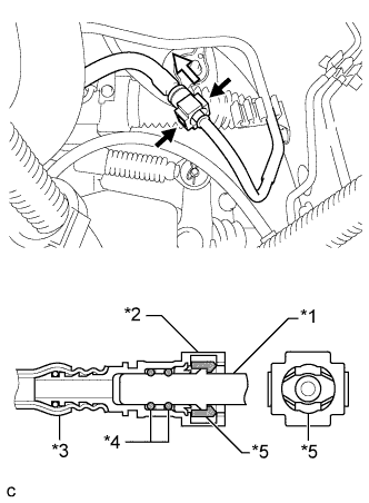 |
Pinch the retainer of the fuel tube connector, and then pull the fuel tube connector off of the fuel pipe.
| *1 | Fuel Pipe |
| *2 | Fuel Tube Connector |
| *3 | Nylon Tube |
| *4 | O-ring |
| *5 | Retainer |
 | Pinch |
 | Pull |
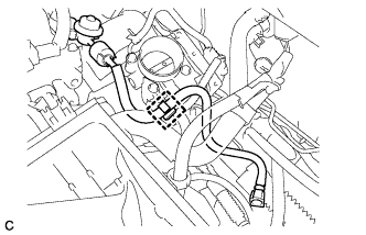 |
Remove the fuel tube sub-assembly from the fuel hose clamp.
| 31. REMOVE FRONT EXHAUST PIPE ASSEMBLY |
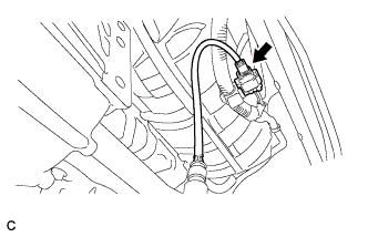 |
Disconnect the oxygen sensor connector.
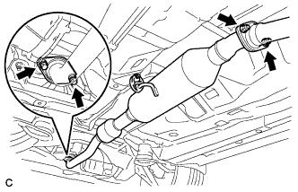 |
Remove the 2 bolts, 2 nuts, 2 compression springs and front exhaust pipe assembly.
Remove the 2 gaskets from the front exhaust pipe assembly and exhaust manifold converter sub-assembly.
| 32. REMOVE FRONT DRIVE SHAFT ASSEMBLY |
| 33. PLACE FRONT WHEELS FACING STRAIGHT AHEAD |
| 34. SECURE STEERING WHEEL |
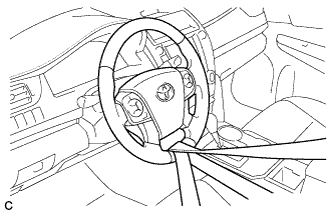 |
Secure the steering wheel with the seat belt in order to prevent rotation.
| 35. SEPARATE STEERING INTERMEDIATE SHAFT ASSEMBLY |
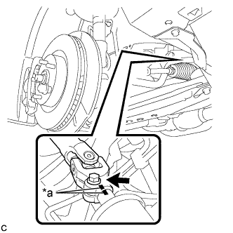 |
Put matchmarks on the steering intermediate shaft assembly and steering link assembly.
| *a | Matchmark |
Remove the bolt.
Separate the steering intermediate shaft assembly from the steering link assembly.
| 36. REMOVE FLYWHEEL HOUSING UNDER COVER |
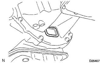 |
Remove the flywheel housing under cover.
| 37. REMOVE DRIVE PLATE AND TORQUE CONVERTER ASSEMBLY SETTING BOLT |
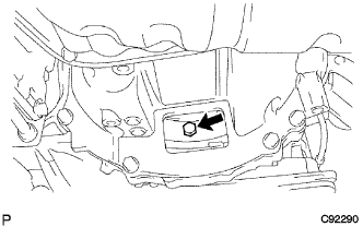 |
Turn the crankshaft to gain access to the removal locations of the 6 drive plate and torque converter assembly setting bolts and remove each bolt while holding the crankshaft pulley bolt with a wrench.
| 38. REMOVE ENGINE ASSEMBLY WITH TRANSAXLE |
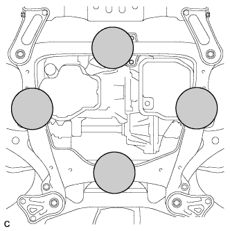 |
Set an engine lifter.
 | Attachment Installation Position |
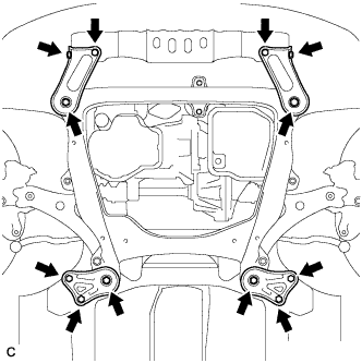 |
Remove the 4 bolts, 2 nuts, and frame side rail plate RH and LH.
Remove the 4 bolts, 2 nuts, and front suspension member brace rear RH and LH.
Operate the engine lifter and remove the engine assembly with transaxle from the vehicle.
Remove the engine wire from the engine assembly with transaxle.
| 39. INSTALL ENGINE HANGERS |
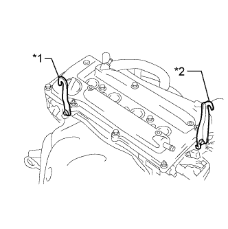 |
Install the 2 engine hangers with the 2 bolts.
| *1 | No. 1 Engine Hanger |
| *2 | No. 2 Engine Hanger |
| Part Name | Part No. |
| No. 1 engine hanger | 12281-28010 |
| No. 2 engine hanger | 12282-28010 |
| Bolt | 91552-B1020 |
| 40. REMOVE V-RIBBED BELT |
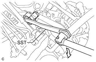 |
Using SST, slowly turn the V-ribbed belt tensioner assembly clockwise.
Remove the V-ribbed belt from each pulley and slowly return the V-ribbed belt tensioner assembly.
| 41. REMOVE COMPRESSOR ASSEMBLY WITH PULLEY |
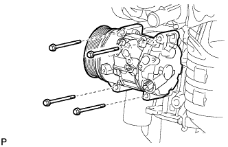 |
Remove the 4 bolts and compressor assembly with pulley.
| 42. REMOVE GENERATOR ASSEMBLY |
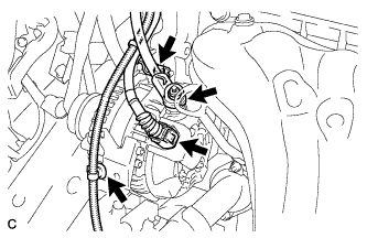 |
Disconnect the connector and wire harness clamp.
Remove the terminal cap.
Remove the nut and disconnect the generator wire.
Remove the bolt and wire harness clamp bracket.
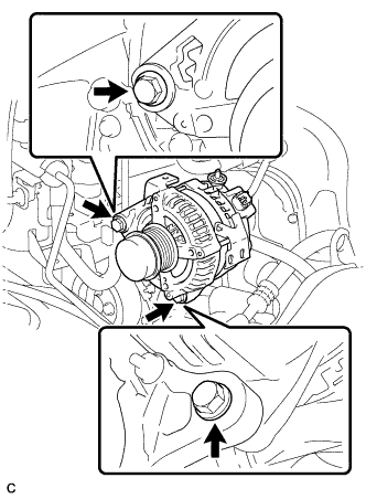 |
Remove the 2 bolts and generator assembly.
| 43. REMOVE FRONT FRAME ASSEMBLY |
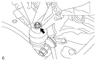 |
Remove the nut and separate the engine mounting insulator LH .
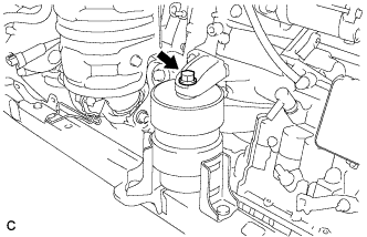 |
Remove the bolt and separate the front engine mounting insulator.
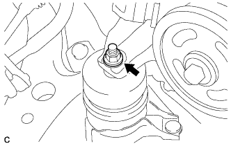 |
Remove the nut and separate the engine mounting insulator RH.
Remove the front frame assembly.
Using a height adjustable attachment and plate lift attachment, place the engine assembly with transaxle on a flat level surface.
| 44. REMOVE FRONT ENGINE MOUNTING INSULATOR |
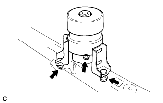 |
Remove the 3 nuts and front engine mounting insulator.
| 45. REMOVE ENGINE MOUNTING INSULATOR LH |
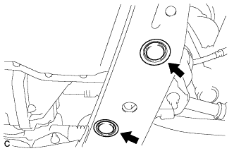 |
Remove the 2 hole plugs from the front frame assembly.
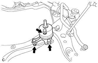 |
Remove the 3 nuts and engine mounting insulator LH.
| 46. REMOVE ENGINE MOUNTING INSULATOR RH |
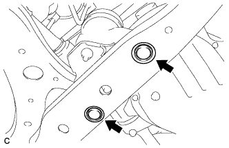 |
Remove the 2 hole plugs from the front frame assembly.
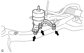 |
Remove the 3 nuts and engine mounting insulator RH.
| 47. REMOVE DRIVE SHAFT BEARING BRACKET |
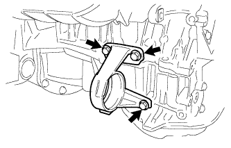 |
Remove the 3 bolts and drive shaft bearing bracket.
| 48. REMOVE ENGINE MOUNTING BRACKET RH |
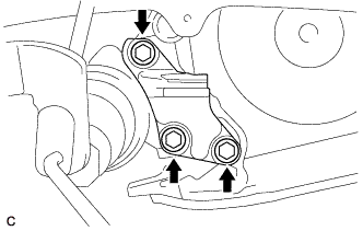 |
Remove the 3 bolts and engine mounting bracket RH.
| 49. DISCONNECT ENGINE WIRE |
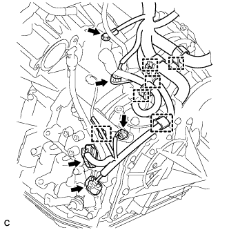 |
Remove the bolt and disconnect the 4 connectors, 6 clamps and engine wire from the automatic transaxle assembly.
| 50. REMOVE AUTOMATIC TRANSAXLE ASSEMBLY |
Using a transmission jack attachment, set the automatic transaxle assembly on a transmission jack.
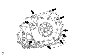 |
Remove the 9 bolts and automatic transaxle assembly.
| 51. REMOVE DRIVE PLATE AND RING GEAR SUB-ASSEMBLY |
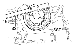 |
Using SST, hold the crankshaft pulley.
| *a | Hold |
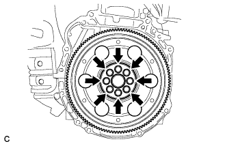 |
Remove the 8 bolts, the front drive plate spacer, the drive plate and ring gear sub-assembly, and the rear drive plate spacer.
| 52. INSTALL ENGINE STAND |
Install the engine onto an engine stand with the bolts.