 |
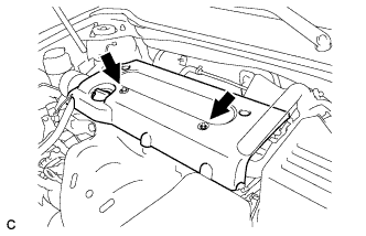
Remove the 2 nuts and No. 1 engine cover sub-assembly.
FUEL INJECTOR > REMOVAL |
| 1. PRECAUTION |
| 2. DISCHARGE FUEL SYSTEM PRESSURE |
| 3. DISCONNECT CABLE FROM NEGATIVE BATTERY TERMINAL |
| 4. REMOVE NO. 1 ENGINE COVER SUB-ASSEMBLY |
|
Remove the 2 nuts and No. 1 engine cover sub-assembly.
| 5. REMOVE WINDSHIELD WIPER MOTOR AND LINK |
| 6. REMOVE FRONT OUTER COWL TOP PANEL SUB-ASSEMBLY |
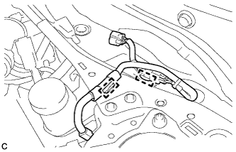 |
Disengage the 2 clamps and separate the wire harness from the front outer cowl top panel sub-assembly.
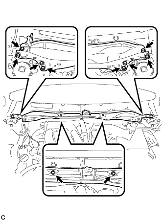 |
Remove the 10 bolts and front outer cowl top panel sub-assembly.
| 7. REMOVE AIR CLEANER CAP SUB-ASSEMBLY |
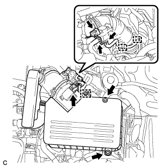 |
Disconnect the vacuum switching valve connector.
Disconnect the 2 vacuum switching valve vacuum hoses.
Disconnect the purge line hose from the 2 clamps.
Disconnect the mass air flow meter connector.
Disconnect the wire harness clamp.
Loosen the 2 bolts and separate the air cleaner cap sub-assembly.
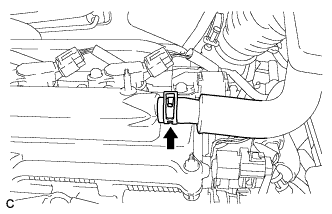 |
Disconnect the ventilation hose from the cylinder head cover sub-assembly.
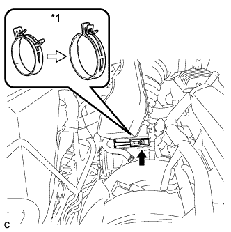 |
Lock the air cleaner hose clamp as shown in the illustration, and disconnect the air cleaner cap sub-assembly from the throttle with motor body assembly.
| *1 | Air Cleaner Hose Clamp |
Remove the air cleaner filter element from the air cleaner case sub-assembly.
| 8. DISCONNECT FUEL TUBE SUB-ASSEMBLY |
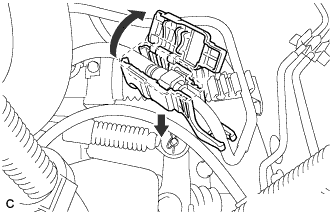 |
Remove the No. 1 fuel pipe clamp.
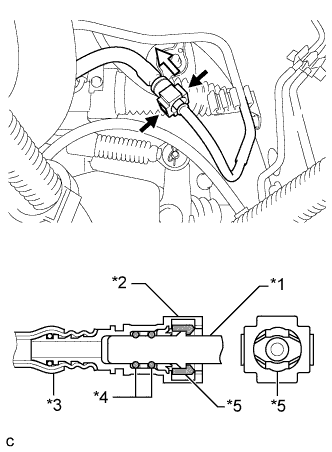 |
Pinch the retainer of the fuel tube connector, and then pull the fuel tube connector off of the fuel pipe.
| *1 | Fuel Pipe |
| *2 | Fuel Tube Connector |
| *3 | Nylon Tube |
| *4 | O-ring |
| *5 | Retainer |
 | Pinch |
 | Pull |
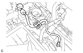 |
Remove the fuel tube sub-assembly from the fuel hose clamp.
| 9. DISCONNECT NO. 2 VENTILATION HOSE |
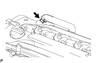 |
Disconnect the No. 2 ventilation hose from the ventilation valve sub-assembly.
| 10. REMOVE FUEL DELIVERY PIPE SUB-ASSEMBLY |
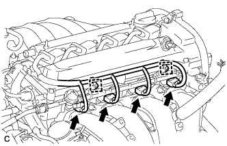 |
Remove the 2 wire harness clamps.
Disconnect the 4 fuel injector connectors.
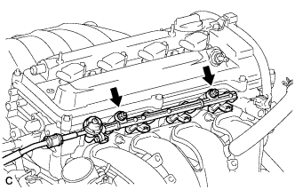 |
Remove the 2 bolts, and then remove the fuel delivery pipe sub-assembly together with the 4 fuel injector assemblies.
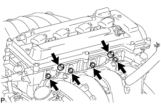 |
Remove the 2 fuel delivery spacers from the cylinder head.
Remove the 4 injector vibration insulators from the cylinder head.
| 11. REMOVE FUEL INJECTOR ASSEMBLY |
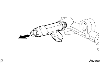 |
Pull the 4 fuel injector assemblies out of the fuel delivery pipe sub-assembly.
| Pull Out |
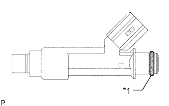 |
Remove the O-ring from each fuel injector assembly.
| *1 | O-ring |
For reinstallation, attach a tag or label with the corresponding cylinder number to each fuel injector shaft.