 |
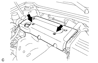
Remove the 2 nuts and No. 1 engine cover sub-assembly.
FUEL PRESSURE PULSATION DAMPER > REMOVAL |
| 1. PRECAUTION |
| 2. DISCHARGE FUEL SYSTEM PRESSURE |
| 3. DISCONNECT CABLE FROM NEGATIVE BATTERY TERMINAL |
| 4. REMOVE NO. 1 ENGINE COVER SUB-ASSEMBLY |
|
Remove the 2 nuts and No. 1 engine cover sub-assembly.
| 5. REMOVE WINDSHIELD WIPER MOTOR AND LINK |
| 6. REMOVE FRONT OUTER COWL TOP PANEL SUB-ASSEMBLY |
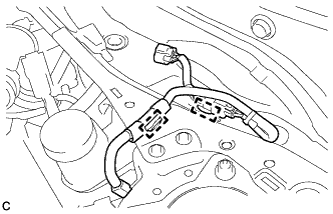 |
Disengage the 2 clamps and separate the wire harness from the front outer cowl top panel sub-assembly.
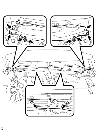 |
Remove the 10 bolts and front outer cowl top panel sub-assembly.
| 7. REMOVE AIR CLEANER CAP SUB-ASSEMBLY |
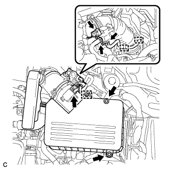 |
Disconnect the vacuum switching valve connector.
Disconnect the 2 vacuum switching valve vacuum hoses.
Disconnect the purge line hose from the 2 clamps.
Disconnect the mass air flow meter connector.
Disconnect the wire harness clamp.
Loosen the 2 bolts and separate the air cleaner cap sub-assembly.
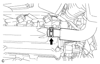 |
Disconnect the ventilation hose from the cylinder head cover sub-assembly.
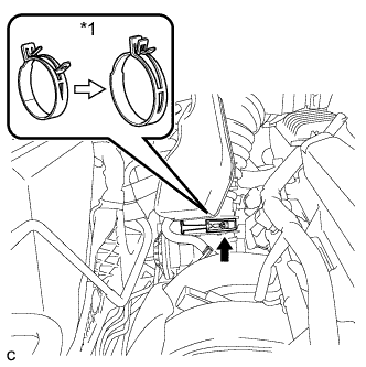 |
Lock the air cleaner hose clamp as shown in the illustration, and disconnect the air cleaner cap sub-assembly from the throttle with motor body assembly.
| *1 | Air Cleaner Hose Clamp |
Remove the air cleaner filter element from the air cleaner case sub-assembly.
| 8. REMOVE FUEL TUBE SUB-ASSEMBLY |
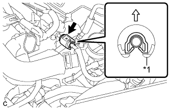 |
Remove the No. 2 fuel pipe clamp.
| *1 | No. 2 Fuel Pipe Clamp |
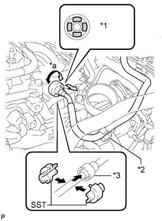 |
Remove the fuel tube sub-assembly from the fuel hose clamp.
| *1 | Retainer |
| *2 | Fuel Hose Clamp |
| *3 | Fuel Tube Connector |
| *a | Turn |
Wipe off any foreign matter on the fuel tube connector.
Hold the fuel tube connector, and then install SST.
Turn SST to align the retainer inside the fuel tube connector with the chamfered part of SST.
Insert SST into the fuel tube connector and hold it. Then push the fuel tube connector toward SST.
Mount the retainer of the fuel tube connector onto the chamfered part of SST.
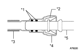 |
Slide SST into the fuel tube connector until it makes a "click" sound, and then disconnect the fuel tube sub-assembly.
| *1 | O-ring |
| *2 | Retainer |
| *3 | Fuel Tube Sub-assembly |
| *4 | Fuel Tube Connector |
| *5 | Fuel Pipe |
| 9. REMOVE FUEL PRESSURE PULSATION DAMPER ASSEMBLY |
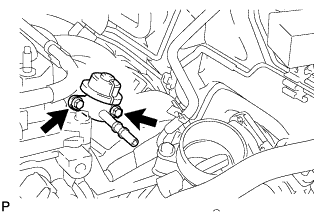 |
Remove the 2 bolts and fuel pressure pulsation damper assembly.
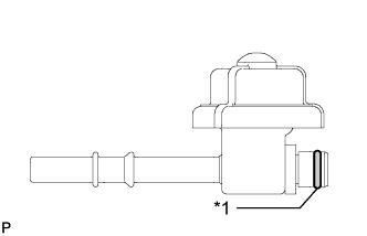 |
Remove the O-ring from the fuel pressure pulsation damper assembly.
| *1 | O-ring |