 |
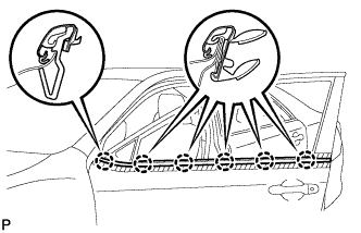
Engage the 6 claws to install the front door belt moulding assembly.
FRONT DOOR BELT MOULDING > INSTALLATION |
| 1. PRECAUTION |
| 2. INSTALL FRONT DOOR BELT MOULDING ASSEMBLY |
|
Engage the 6 claws to install the front door belt moulding assembly.
| 3. INSTALL FRONT DOOR GLASS SUB-ASSEMBLY |
Connect the cable to the negative (-) battery terminal.
Connect the multiplex network master switch assembly and move the front door glass sub-assembly so that the door glass bolts can be seen.
Disconnect the cable from the negative (-) battery terminal.
Disconnect the multiplex network master switch assembly.
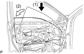 |
Insert the front door glass sub-assembly into the front door panel along the front door glass run as indicated by the arrows, in the order shown in the illustration.
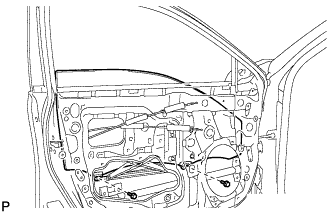 |
Install the front door glass sub-assembly with the 2 bolts.
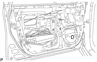 |
Install the grommet.
| 4. INSTALL FRONT DOOR SERVICE HOLE COVER |
Apply new butyl tape to the front door panel.
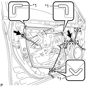 |
Pass the front door lock remote control cable assembly and front door inside locking cable assembly through a new front door service hole cover.
| *1 | Reference Point |
Attach the front door service hole cover according to the reference points on the front door panel.
Engage the 4 clamps.
Connect each connector.
| 5. INSTALL OUTER REAR VIEW MIRROR ASSEMBLY |
| 6. CONNECT CABLE TO NEGATIVE BATTERY TERMINAL |
| 7. INITIALIZE POWER WINDOW CONTROL SYSTEM |
| 8. INSPECT POWER WINDOW OPERATION |