 |
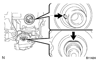
Set the crankshaft key into the left horizontal position.
OIL PUMP > INSTALLATION |
| 1. INSTALL OIL PUMP ASSEMBLY |
Install a new oil pump gasket and the oil pump assembly with the 3 bolts.
| 2. INSTALL NO. 2 CHAIN SUB-ASSEMBLY |
|
Set the crankshaft key into the left horizontal position.
Turn the oil pump drive shaft so that the cutout faces upward.
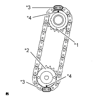 |
Align the yellow mark links with the timing marks of each gear as shown in the illustration.
| *1 | Oil Pump Drive Gear |
| *2 | Oil Pump Drive Shaft Gear |
| *3 | Mark Link |
| *4 | Timing Mark |
Install the sprockets onto the crankshaft and oil pump shaft with the No. 2 chain sub-assembly on the gears.
Temporarily tighten the oil pump drive shaft gear with the nut.
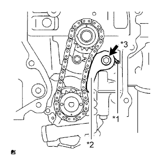 |
Insert the chain damper spring into the adjusting hole, and then install the chain tensioner plate with the bolt.
| *1 | Spring |
| *2 | Chain Tensioner Plate |
| *3 | Bolt |
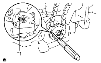 |
Align the adjusting hole of the oil pump drive shaft gear with the groove of the oil pump assembly.
| *1 | Groove |
Insert a 4 mm diameter bar into the adjusting hole of the oil pump drive shaft gear to lock the gear in position, and then tighten the nut.
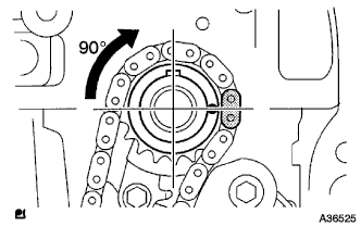 |
Rotate the crankshaft 90° clockwise, and position the crankshaft key to face up as shown in the illustration.
| 3. INSTALL CRANKSHAFT TIMING SPROCKET |
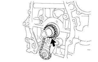 |
Install the crankshaft timing sprocket to the crankshaft.
| 4. INSTALL NO. 1 CHAIN VIBRATION DAMPER |
Install the No. 1 chain vibration damper with the 2 bolts.
| 5. INSTALL CHAIN SUB-ASSEMBLY |
Set the No. 1 cylinder to TDC/compression.
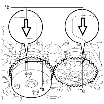 |
Using the hexagonal portion of the camshafts, rotate the camshafts with a wrench, align the timing marks on the camshaft timing gear assembly and camshaft timing sprocket with the front marks located on the No. 1 camshaft bearing cap and No. 2 camshaft bearing cap as shown in the illustration.
| *a | Timing Mark |
| *b | Front Mark |
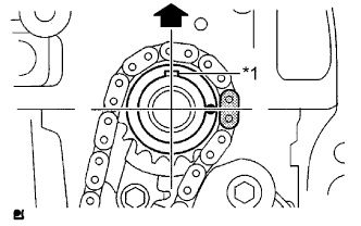 |
Check that the crankshaft is positioned with the crankshaft key facing up as shown in the illustration.
| *1 | Crankshaft Key |
 | Up |
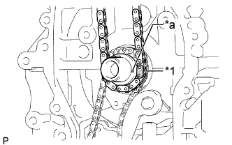 |
Install the chain onto the crankshaft timing sprocket with the gold or pink mark link aligned with the timing mark on the crankshaft.
| *1 | Mark Link |
| *a | Timing Mark |
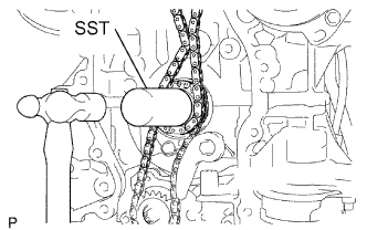 |
Using SST and a hammer, tap in the crankshaft timing sprocket.
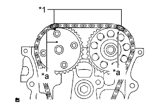 |
Align the gold or yellow links with the timing marks located on the camshaft timing gear assembly and camshaft timing sprocket, then install the chain sub-assembly.
| *1 | Mark Link |
| *a | Timing Mark |
| 6. INSTALL CHAIN TENSIONER SLIPPER |
Install the chain tensioner slipper with the bolt.
| 7. INSTALL TIMING CHAIN GUIDE |
Install the timing chain guide with the bolt.
| 8. INSTALL NO. 1 CRANKSHAFT POSITION SENSOR PLATE |
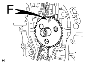 |
Install the No. 1 crankshaft position sensor plate with the "F" mark facing forward.
| 9. INSTALL TIMING CHAIN COVER OIL SEAL |
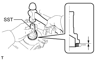 |
Using SST, tap in a new timing chain cover oil seal until its surface is flush with the timing chain cover sub-assembly edge.
Apply a light coat of MP grease to the lip of the timing chain cover oil seal.
| 10. INSTALL TIMING CHAIN COVER SUB-ASSEMBLY |
Remove any old packing material and be careful not to drop any oil on the contact surfaces of the timing chain cover sub-assembly, cylinder head and cylinder block.
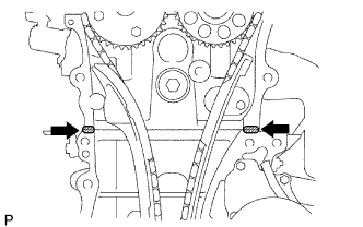 |
Apply seal packing (diameter 4.0 to 4.5 mm (0.157 to 0.177 in.)) as shown in the illustration.
| Seal Packing |
Apply a continuous bead of seal packing as shown in the illustration.
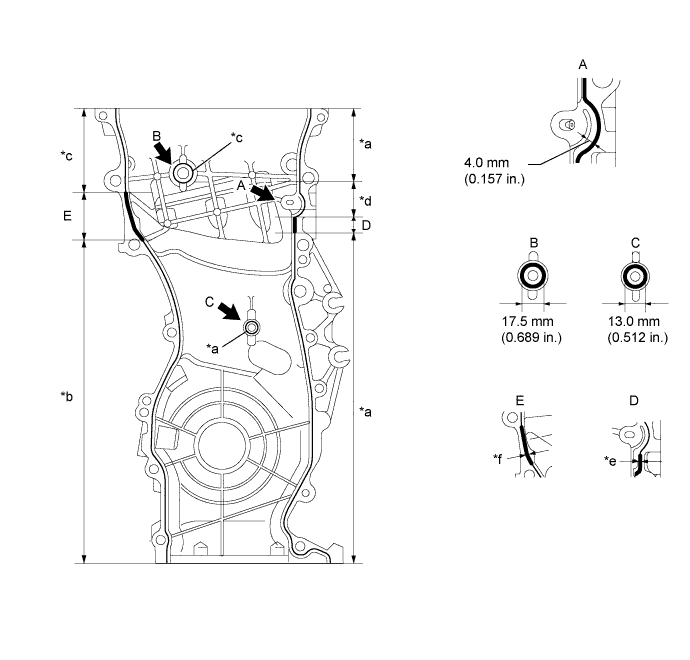
| *a | Seal Diameter: 2.5 to 3.0 mm (0.0984 to 0.118 in.) | *b | Seal Diameter: 3.0 mm (0.118 in.) |
| *c | Seal Diameter: 4.0 mm (0.157 in.) | *d | Seal Diameter: 4.0 to 4.5 mm (0.157 to 0.177 in.) |
| *e | Seal Diameter: 4.5 to 5.0 mm (0.177 to 0.197 in.) | *f | Seal Diameter: 5.5 to 6.0 mm (0.217 to 0.236 in.) |
 | Seal Packing | - | - |
Apply adhesive to the threads of the bolt A.
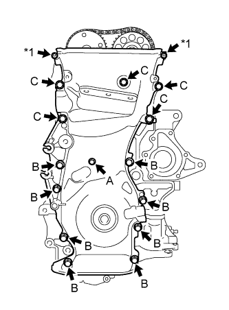 |
Temporarily install the timing chain cover sub-assembly with the 12 bolts and 2 nuts.
| *1 | Nut |
| Item | Length |
| Bolt A | 30 mm (1.18 in.) length for 10 mm head |
| Bolt B | 30 mm (1.18 in.) length for 12 mm head |
| Bolt C | 40 mm (1.57 in.) length for 14 mm head |
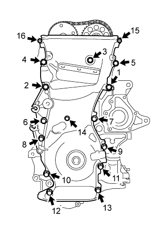 |
Fully tighten the bolts and nuts in the order shown in the illustration.
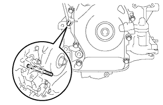 |
Using an E10 "TORX" socket wrench, install the stud bolt for the V-ribbed belt tensioner assembly.
| 11. INSTALL NO. 1 CHAIN TENSIONER ASSEMBLY |
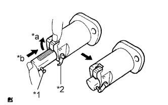 |
Release the ratchet pawl, then fully push in the plunger and set the hook to the pin so that the plunger is in the position shown in the illustration.
| *1 | Pin |
| *2 | Hook |
| *a | Raise |
| *b | Push |
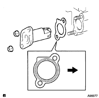 |
Install a new chain tensioner gasket and the No. 1 chain tensioner assembly with the 2 nuts.
| Engine Front |
| 12. INSTALL V-RIBBED BELT TENSIONER ASSEMBLY |
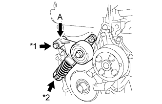 |
Temporarily install the V-ribbed belt tensioner assembly with the nut.
| *1 | Bolt |
| *2 | Nut |
Slightly push down on the V-ribbed belt tensioner assembly at part (A) to align the holes of the engine and tensioner as shown in the illustration, and temporarily install the bolt.
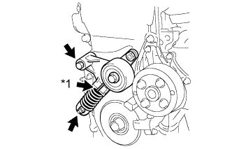 |
Tighten the bolt and nut to install the V-ribbed belt tensioner.
| *1 | Pin |
| 13. INSTALL CRANKSHAFT PULLEY |
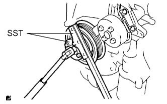 |
Using SST, secure the pulley in place and tighten the bolt.
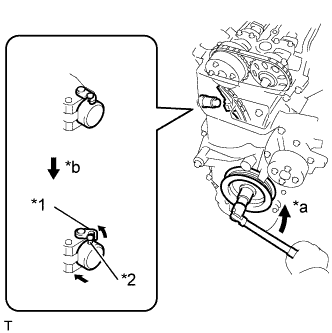 |
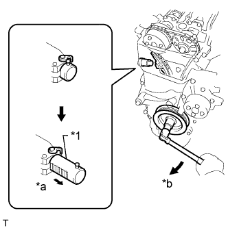
Turn the crankshaft counterclockwise, then disconnect the hook from the pin.
| *1 | Hook |
| *2 | Pin |
| *a | Turn |
| *b | Disconnect |
 |
Turn the crankshaft clockwise, then check that the plunger is extended.
| *1 | Plunger |
| *a | Extend |
| *b | Turn |
| 14. INSTALL OIL PAN SUB-ASSEMBLY |
Remove any old packing material and be careful not to drop any oil on the contact surfaces of the cylinder block and oil pan sub-assembly.
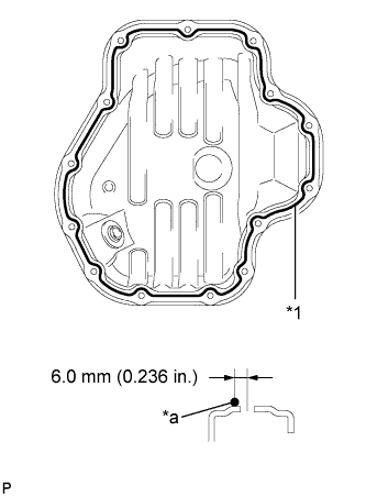 |
Apply a continuous bead of seal packing (diameter 3.0 to 4.0 mm (0.118 to 0.157 in.)) as shown in the illustration.
| *1 | Seal Packing |
| *a | Seal Diameter: 4.0 to 4.5 mm |
Install the oil pan sub-assembly onto the cylinder block.
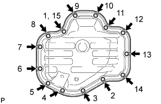 |
Uniformly tighten the 12 bolts and 2 nuts in the sequence shown in the illustration.
| 15. INSTALL CRANK POSITION SENSOR |
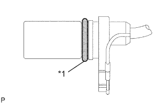 |
Apply a light coat of engine oil to the O-ring on the crank position sensor.
| *1 | New O-ring |
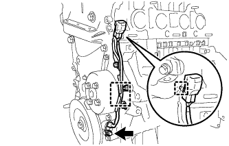 |
Install the crank position sensor with the bolt.
Install the 2 wire harness clamps.
| 16. INSTALL IDLER PULLEY BRACKET |
Install the idler pulley bracket with the 2 bolts.
| 17. INSTALL CYLINDER HEAD COVER GASKET |
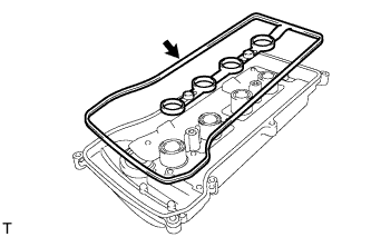 |
Install a new cylinder head cover gasket onto the cylinder head cover sub-assembly.
| 18. INSTALL CYLINDER HEAD COVER SUB-ASSEMBLY |
Remove any old packing material from the contact surfaces.
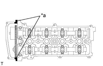 |
Apply seal packing to the 2 locations shown in the illustration.
| *a | Seal Packing |
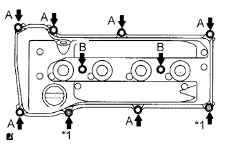 |
Install the cylinder head cover sub-assembly with the 8 bolts and 2 nuts.
| *1 | Nut |
| 19. INSTALL IGNITION COIL ASSEMBLY |
Install the 4 ignition coil assemblies with the 4 bolts.
Connect the 4 ignition coil assembly connectors.
| 20. INSTALL ENGINE HANGERS |
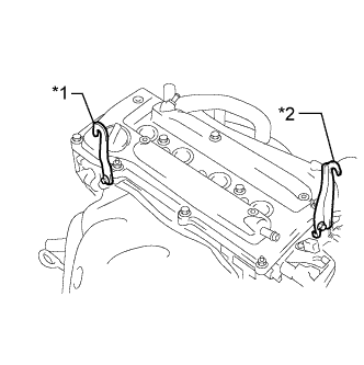 |
Install the 2 engine hangers with the 2 bolts.
| *1 | No. 1 Engine Hanger |
| *2 | No. 2 Engine Hanger |
| Part Name | Part No. |
| No. 1 engine hanger | 12281-28010 |
| No. 2 engine hanger | 12282-28010 |
| Bolt | 91552-B1020 |
| 21. REMOVE ENGINE STAND |