 |
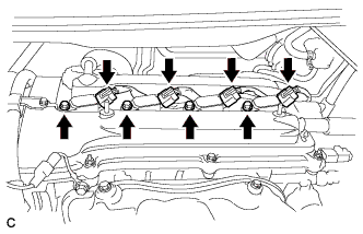
Disconnect the 4 ignition coil assembly connectors.
OIL PUMP > REMOVAL |
| 1. INSTALL ENGINE STAND |
| 2. REMOVE ENGINE HANGERS |
Remove the 2 bolts and 2 engine hangers.
| 3. REMOVE IGNITION COIL ASSEMBLY |
|
Disconnect the 4 ignition coil assembly connectors.
Remove the 4 bolts and 4 ignition coil assemblies.
| 4. REMOVE CYLINDER HEAD COVER SUB-ASSEMBLY |
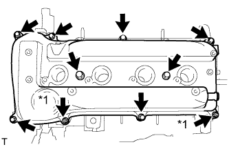 |
Remove the 8 bolts and 2 nuts, and remove the cylinder head cover sub-assembly.
| *1 | Nut |
| 5. REMOVE CYLINDER HEAD COVER GASKET |
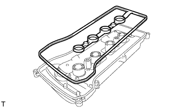 |
Remove the cylinder head cover gasket from the cylinder head cover sub-assembly.
| 6. REMOVE IDLER PULLEY BRACKET |
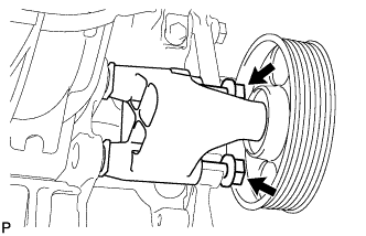 |
Loosen the 2 bolts and remove the idler pulley bracket with the 2 bolts.
| 7. REMOVE OIL PAN SUB-ASSEMBLY |
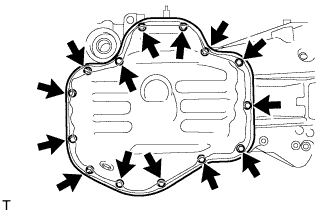 |
Remove the 12 bolts and 2 nuts.
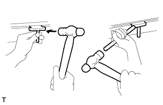 |
Insert the blade of an oil pan seal cutter between the crankcase, chain cover and oil pan, then cut through the applied sealer and remove the oil pan sub-assembly.
| 8. SET NO. 1 CYLINDER TO TDC/COMPRESSION |
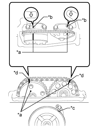 |
Turn the crankshaft pulley until its groove and the timing mark "0" of the timing chain cover sub-assembly are aligned.
| *a | Timing Mark |
| *b | Front Mark |
| *c | Groove |
| *d | Paint Mark |
Check that each timing mark of the camshaft timing gear assembly and camshaft timing sprocket is aligned with each front mark located on the No. 1 and No. 2 bearing caps as shown in the illustration.
If not, turn the crankshaft by 1 revolution (360°) to align the timing marks as above.
Place paint marks on the chain sub-assembly in alignment with the timing marks on the camshaft timing gear assembly and camshaft timing sprocket.
| 9. REMOVE CRANKSHAFT PULLEY |
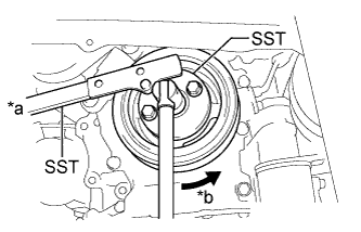 |
Using SST, hold the crankshaft pulley and loosen the pulley bolt. Further loosen the bolt until 2 or 3 threads are screwed into the crankshaft.
| *a | Hold |
| *b | Turn |
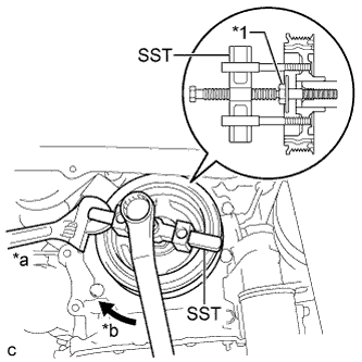 |
Using SST and the pulley bolt, remove the crankshaft pulley.
| *1 | Pulley Bolt |
| *a | Hold |
| *b | Turn |
| 10. REMOVE NO. 1 CHAIN TENSIONER ASSEMBLY |
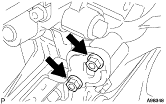 |
Remove the 2 nuts, No. 1 chain tensioner assembly and chain tensioner gasket.
| 11. REMOVE V-RIBBED BELT TENSIONER ASSEMBLY |
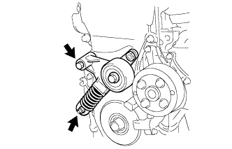 |
Remove the bolt, nut and V-ribbed belt tensioner assembly.
| 12. REMOVE CRANK POSITION SENSOR |
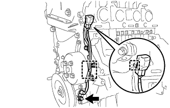 |
Disconnect the 2 wire harness clamps.
Remove the bolt and crank position sensor.
| 13. REMOVE TIMING CHAIN COVER SUB-ASSEMBLY |
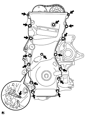 |
Using an E10 "TORX" socket wrench, remove the stud bolt for the V-ribbed belt tensioner assembly.
Remove the 12 bolts and 2 nuts.
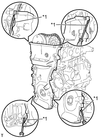 |
Remove the timing chain cover sub-assembly by prying the portions between the timing chain cover sub-assembly, cylinder head and cylinder block with a screwdriver.
| *1 | Protective Tape |
| 14. REMOVE TIMING CHAIN COVER OIL SEAL |
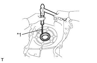 |
Place the timing chain cover sub-assembly on wooden blocks.
| *1 | Protective Tape |
Using a screwdriver, pry out the timing chain cover oil seal.
| 15. REMOVE NO. 1 CRANKSHAFT POSITION SENSOR PLATE |
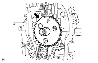 |
Remove the No. 1 crankshaft position sensor plate.
| 16. REMOVE TIMING CHAIN GUIDE |
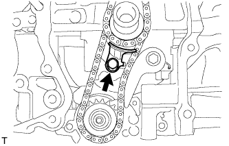 |
Remove the bolt and timing chain guide.
| 17. REMOVE CHAIN TENSIONER SLIPPER |
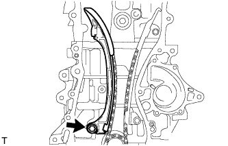 |
Remove the bolt and chain tensioner slipper.
| 18. REMOVE NO. 1 CHAIN VIBRATION DAMPER |
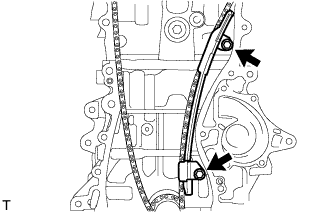 |
Remove the 2 bolts and No. 1 chain vibration damper.
| 19. REMOVE CHAIN SUB-ASSEMBLY |
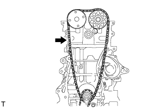 |
Remove the chain sub-assembly.
| 20. REMOVE CRANKSHAFT TIMING SPROCKET |
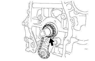 |
Remove the crankshaft timing sprocket from the crankshaft.
| 21. REMOVE NO. 2 CHAIN SUB-ASSEMBLY |
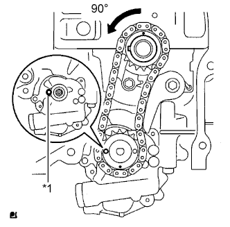 |
Turn the crankshaft 90° counterclockwise to align the adjusting hole on the oil pump drive shaft sprocket with the groove on the oil pump assembly.
| *1 | Groove |
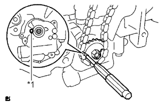 |
Insert a 4 mm diameter bar into the adjusting hole of the oil pump drive shaft sprocket to lock the gear in position, and then remove the nut.
| *1 | Groove |
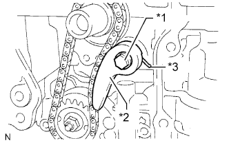 |
Remove the bolt, chain tensioner plate and chain damper spring.
| *1 | Bolt |
| *2 | Chain Tensioner Plate |
| *3 | Chain Damper Spring |
Remove the oil pump drive sprocket, oil pump drive shaft sprocket and No. 2 chain sub-assembly.
| 22. REMOVE OIL PUMP ASSEMBLY |
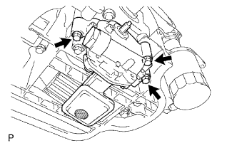 |
Remove the 3 bolts, oil pump assembly and oil pump gasket.