 |
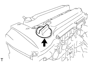
Remove the oil filler cap sub-assembly from the cylinder head cover sub-assembly.
ENGINE UNIT > DISASSEMBLY |
| 1. REMOVE OIL FILLER CAP SUB-ASSEMBLY |
|
Remove the oil filler cap sub-assembly from the cylinder head cover sub-assembly.
| 2. REMOVE OIL FILLER CAP GASKET |
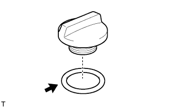 |
Remove the oil filler cap gasket from the oil filler cap sub-assembly.
| 3. REMOVE VENTILATION VALVE SUB-ASSEMBLY |
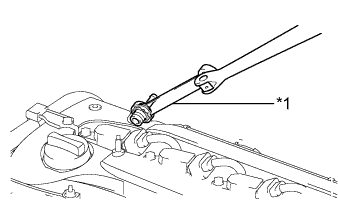 |
Using a ball joint lock nut wrench (22 mm), remove the ventilation valve sub-assembly.
| *1 | Ball Joint Lock Nut Wrench (22 mm) |
| 4. REMOVE SPARK PLUG |
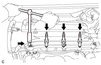 |
Remove the 4 spark plugs.
| 5. REMOVE OIL FILTER SUB-ASSEMBLY |
Using SST, remove the oil filter sub-assembly.
| 6. REMOVE OIL FILTER UNION |
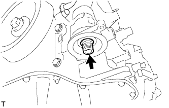 |
Using a 12 mm socket hexagon wrench, remove the oil filter union.
| 7. REMOVE CYLINDER HEAD COVER SUB-ASSEMBLY |
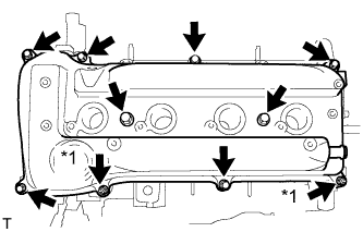 |
Remove the 8 bolts and 2 nuts, and remove the cylinder head cover sub-assembly.
| *1 | Nut |
| 8. REMOVE CYLINDER HEAD COVER GASKET |
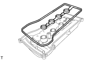 |
Remove the cylinder head cover gasket from the cylinder head cover sub-assembly.
| 9. REMOVE V-RIBBED BELT TENSIONER ASSEMBLY |
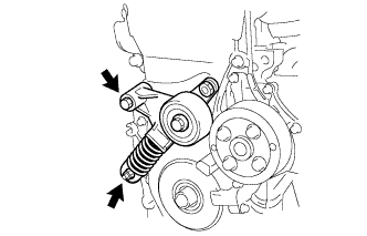 |
Remove the bolt, nut and V-ribbed belt tensioner assembly.
| 10. REMOVE CRANK POSITION SENSOR |
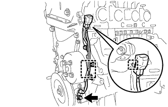 |
Disconnect the 2 wire harness clamps.
Remove the bolt and crank position sensor.
| 11. REMOVE CAMSHAFT POSITION SENSOR |
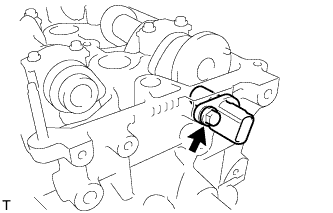 |
Remove the bolt and camshaft position sensor.
| 12. SET NO. 1 CYLINDER TO TDC/COMPRESSION |
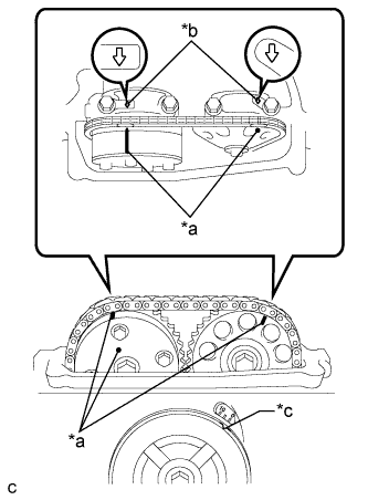 |
Turn the crankshaft pulley until the groove and the timing mark "0" on the timing chain cover sub-assembly are aligned.
| *a | Timing Mark |
| *b | Front Mark |
| *c | Groove |
Check that each timing mark on the camshaft timing gear assembly and camshaft timing sprocket with the front marks located on the No. 1 and No. 2 bearing caps as shown in the illustration.
If not, turn the crankshaft pulley 1 revolution (360°) to align the timing marks as illustrated.
| 13. REMOVE CRANKSHAFT PULLEY |
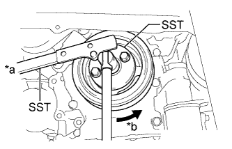 |
Using SST, hold the crankshaft pulley and loosen the pulley bolt. Further loosen the bolt until 2 or 3 threads are screwed into the crankshaft.
| *a | Hold |
| *b | Turn |
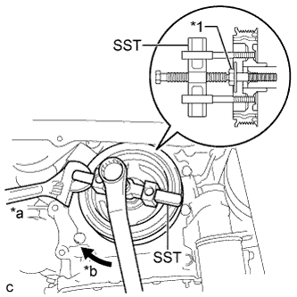 |
Using SST and the pulley bolt, remove the crankshaft pulley.
| *1 | Pulley Bolt |
| *a | Hold |
| *b | Turn |
| 14. REMOVE CAMSHAFT TIMING OIL CONTROL VALVE ASSEMBLY |
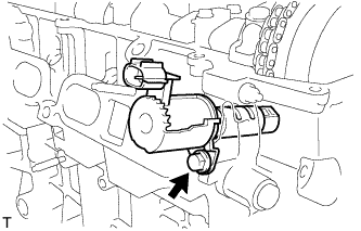 |
Remove the bolt and camshaft timing oil control valve assembly from the cylinder head sub-assembly.
Remove the O-ring from the camshaft timing oil control valve assembly.
| 15. REMOVE NO. 1 CHAIN TENSIONER ASSEMBLY |
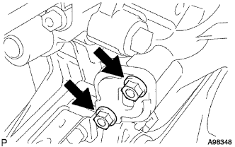 |
Remove the 2 nuts, No. 1 chain tensioner assembly and chain tensioner gasket.
| 16. REMOVE WATER PUMP PULLEY |
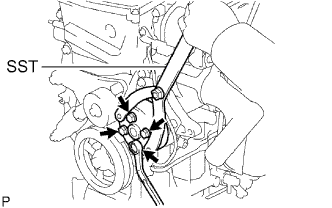 |
Using SST, remove the 4 bolts and water pump pulley.
| 17. REMOVE ENGINE WATER PUMP ASSEMBLY |
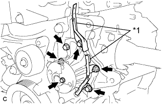 |
Remove the 4 bolts, 2 nuts and 2 wire harness clamp brackets.
| *1 | Wire Harness Clamp Bracket |
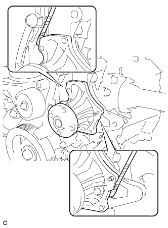 |
Using a screwdriver, pry between the engine water pump assembly and cylinder block, and then remove the water pump.
| 18. REMOVE OIL PAN DRAIN PLUG |
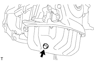 |
Remove the oil pan drain plug and gasket from the oil pan sub-assembly.
| 19. REMOVE OIL PAN SUB-ASSEMBLY |
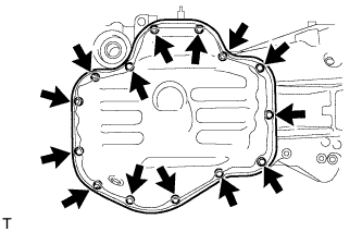 |
Remove the 12 bolts and 2 nuts.
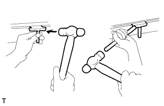 |
Insert the blade of an oil pan seal cutter between the crankcase, chain cover and oil pan, then cut through the applied sealer and remove the oil pan sub-assembly.
| 20. REMOVE TIMING CHAIN COVER SUB-ASSEMBLY |
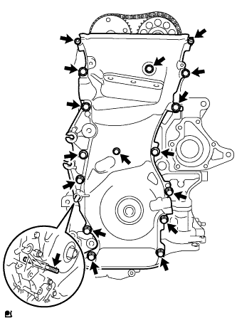 |
Using an E10 "TORX" socket wrench, remove the stud bolt for the V-ribbed belt tensioner assembly.
Remove the 12 bolts and 2 nuts.
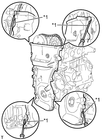 |
Remove the timing chain cover sub-assembly by prying the portions between the timing chain cover sub-assembly, cylinder head and cylinder block with a screwdriver.
| *1 | Protective Tape |
| 21. REMOVE TIMING CHAIN COVER OIL SEAL |
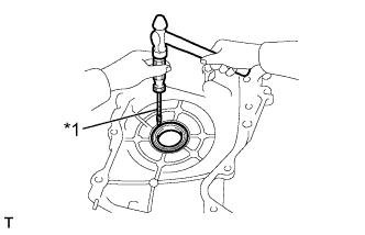 |
Place the timing chain cover sub-assembly on wooden blocks.
| *1 | Protective Tape |
Using a screwdriver, pry out the timing chain cover oil seal.
| 22. REMOVE NO. 1 CRANKSHAFT POSITION SENSOR PLATE |
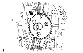 |
Remove the No. 1 crankshaft position sensor plate.
| 23. REMOVE TIMING CHAIN GUIDE |
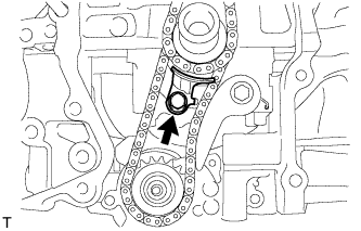 |
Remove the bolt and timing chain guide.
| 24. REMOVE CHAIN TENSIONER SLIPPER |
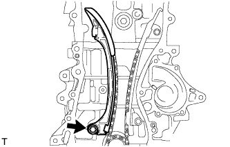 |
Remove the bolt and chain tensioner slipper.
| 25. REMOVE NO. 1 CHAIN VIBRATION DAMPER |
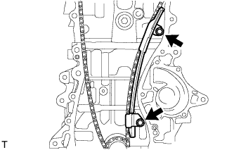 |
Remove the 2 bolts and No. 1 chain vibration damper.
| 26. REMOVE CHAIN SUB-ASSEMBLY |
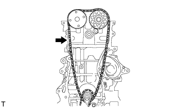 |
Remove the chain sub-assembly.
| 27. REMOVE CRANKSHAFT TIMING SPROCKET |
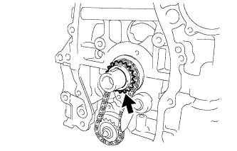 |
Remove the crankshaft timing sprocket from the crankshaft.
| 28. REMOVE NO. 2 CHAIN SUB-ASSEMBLY |
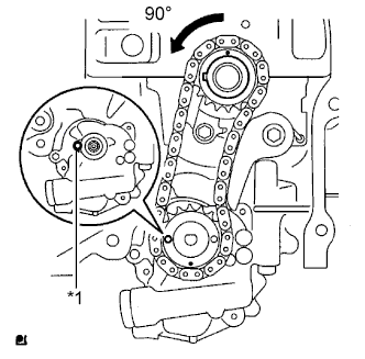 |
Turn the crankshaft 90° counterclockwise to align the adjusting hole on the oil pump drive shaft sprocket with the groove on the oil pump assembly.
| *1 | Groove |
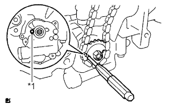 |
Insert a 4 mm diameter bar into the adjusting hole of the oil pump drive shaft sprocket to lock the gear in position, and then remove the nut.
| *1 | Groove |
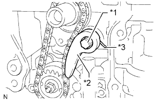 |
Remove the bolt, chain tensioner plate and chain damper spring.
| *1 | Bolt |
| *2 | Chain Tensioner Plate |
| *3 | Chain Damper Spring |
Remove the oil pump drive sprocket, oil pump drive shaft sprocket and No. 2 chain sub-assembly.
| 29. REMOVE CRANKSHAFT PULLEY SET KEY |
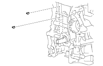 |
Remove the 2 crankshaft pulley set keys from the crankshaft.
| 30. REMOVE NO. 2 CAMSHAFT |
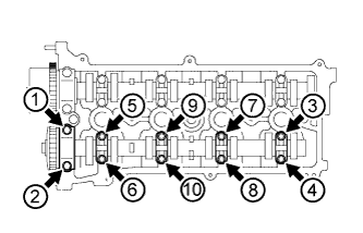 |
Using several steps, uniformly loosen and remove the 10 bearing cap bolts in the sequence shown in the illustration.
Remove the 5 bearing caps.
Remove the No. 2 camshaft.
| 31. REMOVE CAMSHAFT |
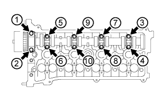 |
Using several steps, uniformly loosen and remove the 10 bearing cap bolts in the sequence shown in the illustration.
Remove the 5 bearing caps.
Remove the camshaft.
| 32. REMOVE NO. 1 CAMSHAFT BEARING |
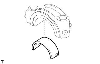 |
Remove the No. 1 camshaft bearing from the No. 1 camshaft bearing cap.
| 33. REMOVE NO. 2 CAMSHAFT BEARING |
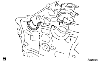 |
Remove the No. 2 camshaft bearing from the cylinder head sub-assembly.
| 34. REMOVE CAMSHAFT TIMING SPROCKET |
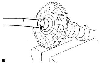 |
Clamp the camshaft in a vise.
Remove the bolt and camshaft timing sprocket.
| 35. REMOVE CAMSHAFT TIMING GEAR ASSEMBLY |
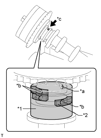 |
Clamp the camshaft in a vise, and make sure that the camshaft timing gear assembly does not rotate.
| *1 | Vinyl Tape |
| *2 | Rubber Piece |
| *a | Open |
| *b | Close |
| *c | Advance Side Path |
Cover all the oil paths with vinyl tape except the advance side path shown in the illustration.
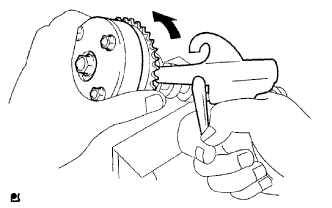 |
Apply air pressure of 150 kPa (1.5 kgf/cm2, 22 psi) to the open oil path, then turn the camshaft timing gear assembly to the advance direction (counterclockwise) by hand.
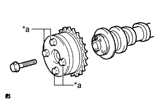 |
Remove the bolt and camshaft timing gear assembly.
| *a | Do Not Remove |
| 36. REMOVE CYLINDER HEAD SUB-ASSEMBLY |
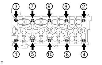 |
Using a 10 mm bi-hexagon wrench, uniformly loosen the 10 cylinder head set bolts in the order shown in the illustration.
Remove the 10 cylinder head set bolts and 10 plate washers.
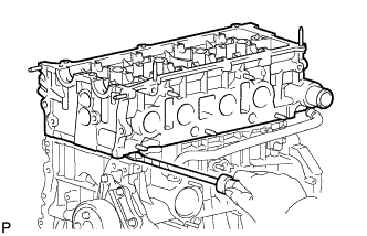 |
Using a screwdriver with its tip wrapped with tape, pry between the cylinder head sub-assembly and cylinder block, and remove the cylinder head sub-assembly.
| 37. REMOVE CYLINDER HEAD GASKET |
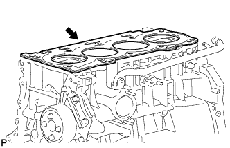 |
Remove the cylinder head gasket.
| 38. REMOVE CYLINDER BLOCK WATER JACKET SPACER |
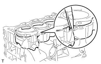 |
Using needle nose pliers, remove the cylinder block water jacket spacer from the water jacket.
| 39. REMOVE WATER INLET HOUSING DRAIN COCK ASSEMBLY |
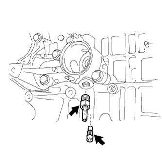 |
Remove the water inlet housing drain cock plug from the water inlet housing drain cock assembly.
Remove the water inlet housing drain cock assembly from the water inlet housing.
| 40. REMOVE WATER INLET HOUSING |
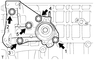 |
Remove the 5 bolts in the order shown in the illustration to remove the water inlet housing from the cylinder block.
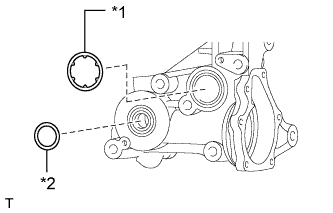 |
Remove the water inlet housing O-ring and water inlet housing gasket from the water inlet housing.
| *1 | Water Inlet Housing O-ring |
| *2 | Water Inlet Housing Gasket |
| 41. REMOVE OIL CONTROL VALVE FILTER |
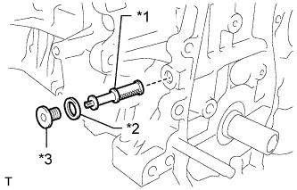 |
Using an 8 mm socket hexagon wrench, remove the screw plug, gasket and oil control valve filter.
| *1 | Oil Control Valve Filter |
| *2 | Gasket |
| *3 | Screw Plug |
| 42. REMOVE NO. 1 TAPER SCREW PLUG |
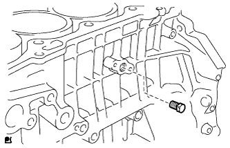 |
Remove the No. 1 taper screw plug from the cylinder block.
| 43. REMOVE OIL PUMP ASSEMBLY |
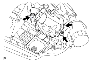 |
Remove the 3 bolts, oil pump assembly and oil pump gasket.
| 44. INSPECT BALANCE SHAFT THRUST CLEARANCE |
Install the balance shafts (Click here).
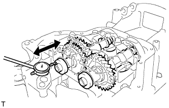 |
Using a dial indicator, measure the thrust clearance while moving the balance shaft back and forth.
| 45. REMOVE BALANCE SHAFT HOUSING |
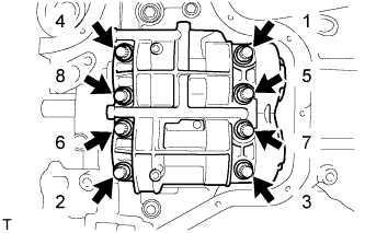 |
Using several steps, uniformly loosen and remove the 8 bolts in the sequence shown in the illustration.
Remove the balance shaft housing from the stiffening crankcase assembly.
| 46. REMOVE NO. 1 AND NO. 2 BALANCE SHAFTS |
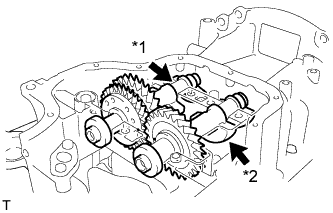 |
Remove the No. 1 and No. 2 balance shafts.
| *1 | No. 1 Balance Shaft |
| *2 | No. 2 Balance Shaft |
| 47. REMOVE NO. 1 BALANCE SHAFT BEARING |
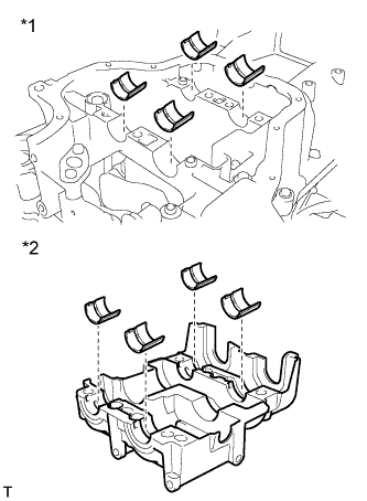 |
Remove the 8 No. 1 balance shaft bearings shown in the illustration.
| *1 | Stiffening Crankcase |
| *2 | Balance Shaft Housing |
| 48. INSPECT BALANCE SHAFT OIL CLEARANCE |
Clean each bearing and journal.
Check each bearing and journal for pitting and scratches.
If a bearing or journal is damaged, replace the bearings. If necessary, replace the balance shaft.
Place the No. 1 and No. 2 balance shafts onto the stiffening crankcase assembly.
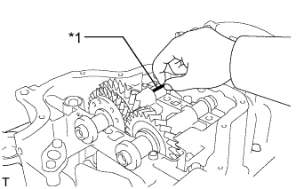 |
Lay a strip of Plastigage across each journal.
| *1 | Plastigage |
Install the balance shaft housing .
Remove the balance shaft housing .
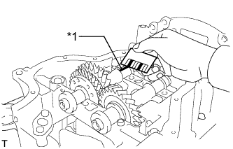 |
Measure the Plastigage at its widest point.
| *1 | Plastigage |
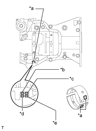 |
If replacing a bearing, select a new one with the same number.
| *a | Number Mark |
| *b | Front No. 1 Journal Bore |
| *c | Rear No. 1 Journal Bore |
| *d | Front No. 2 Journal Bore |
| *e | Rear No. 2 Journal Bore |
| Item | Specified Condition |
| Mark 1 | 26.000 to 26.006 mm (1.0236 to 1.0239 in.) |
| Mark 2 | 26.007 to 26.012 mm (1.0239 to 1.0241 in.) |
| Mark 3 | 26.013 to 26.018 mm (1.0241 to 1.0243 in.) |
| Item | Specified Condition |
| Mark 1 | 1.486 to 1.489 mm (0.05850 to 0.05862 in.) |
| Mark 2 | 1.490 to 1.492 mm (0.05866 to 0.05874 in.) |
| Mark 3 | 1.493 to 1.495 mm (0.0588 to 0.0589 in.) |
Inspect the balance shaft housing bolts.
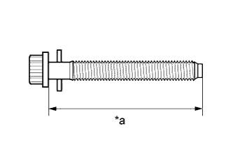 |
Using a vernier caliper, measure the length of the balance shaft housing bolts from the seat to the end.
| *a | Measurement Length |
| 49. REMOVE REAR ENGINE OIL SEAL |
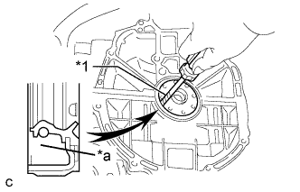 |
Using a knife, cut off the lip of the rear engine oil seal.
| *1 | Protective Tape |
| *a | Cut Position |
Using a screwdriver, pry out the rear engine oil seal.
| 50. REMOVE STIFFENING CRANKCASE ASSEMBLY |
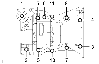 |
Uniformly loosen and remove the 11 bolts in the sequence shown in the illustration.
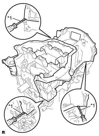 |
Using a screwdriver with its tip wrapped with protective tape, remove the stiffening crankcase assembly by prying between the stiffening crankcase assembly and cylinder block.
| *1 | Protective Tape |