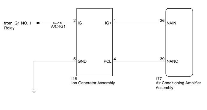
DTC B14B9 Open in Ion Generator Circuit |
| DTC No. | DTC Detection Condition | Trouble Area |
| B14B9 | Open in ion generator assembly circuit |
|
| 1.PERFORM ACTIVE TEST USING INTELLIGENT TESTER |
Connector the intelligent tester to the DLC3.
Turn the Ignition switch to ON.
Turn the intelligent tester on.
Enter the following menus: Body / Air Conditioner / Active Test.
Check the operation by referring to the table below.
| Tester Display | Test Part | Control Range | Diagnostic Note |
| Ion Generator | Ion generator assembly | OFF, ON | - |
| Result | Proceed to |
| NG | A |
| OK (When troubleshooting according to Problem Symptoms Table) | B |
| OK (When troubleshooting according to the DTC) | C |
|
| ||||
|
| ||||
| A | |
 |
| 2.CHECK HARNESS AND CONNECTOR (ION GENERATOR ASSEMBLY - BODY GROUND) |
Disconnect the I16 ion generator assembly connector.
Measure the resistance according to the value(s) in the table below.
| Tester Connection | Condition | Specified Condition |
| I16-5 (GND) - Body ground | Always | Below 1 Ω |
|
| ||||
| OK | |
|
| 3.CHECK HARNESS AND CONNECTOR (ION GENERATOR ASSEMBLY - IG CIRCUIT) |
Measure the voltage according to the value(s) in the table below.
| Tester Connection | Condition | Specified Condition |
| I16-2 (IG) - Body ground | Ignition switch off | Below 1 V |
| I16-2 (IG) - Body ground | Ignition switch ON | 11 to 14 V |
|
| ||||
| OK | |
|
| 4.CHECK HARNESS AND CONNECTOR (ION GENERATOR ASSEMBLY - AIR CONDITIONING AMPLIFIER ASSEMBLY) |
Disconnect the I77 air conditioning amplifier assembly connector.
Measure the resistance according to the value(s) in the table below.
| Tester Connection | Condition | Specified Condition |
| I77-26 (NAIN) - I16-1 (IG+) | Always | Below 1 Ω |
| I77-39 (NANO) - I16-4 (PCL) | Always | Below 1 Ω |
| I77-26 (NAIN) - Body ground | Always | 10 kΩ or higher |
| I77-39 (NANO) - Body ground | Always | 10 kΩ or higher |
|
| ||||
| OK | |
|
| 5.REPLACE ION GENERATOR ASSEMBLY |
Replace the ion generator assembly (Click here).
Check for the DTC.
| Result | Proceed to |
| DTC B14B9 is output | A |
| DTC B14B9 is not output | B |
|
| ||||
| A | ||
 | ||
| ||
