 |
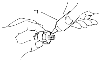
Apply adhesive to 2 or 3 threads of the oil pressure switch.
| *1 | Adhesive |
- Adhesive:
- TOYOTA Genuine Adhesive 1344, Three Bond 1344 or equivalent.
- NOTICE:
- Do not let adhesive adhere to the oil hole.
ENGINE UNIT > INSTALLATION |
| 1. INSTALL IGNITION COIL ASSEMBLY |
Install the 4 ignition coil assemblies with the 4 bolts.
Connect the 4 ignition coil assembly connectors.
| 2. INSTALL ENGINE COOLANT TEMPERATURE SENSOR |
Install a new gasket to the engine coolant temperature sensor.
Using a 19 mm ball joint lock nut wrench, install the engine coolant temperature sensor.
Connect the engine coolant temperature sensor connector.
Install the wire harness with the 2 bolts.
| 3. INSTALL ENGINE OIL PRESSURE SWITCH ASSEMBLY |
|
Apply adhesive to 2 or 3 threads of the oil pressure switch.
| *1 | Adhesive |
Using a 24 mm deep socket wrench, install the oil pressure switch.
Connect the connector.
| 4. INSTALL KNOCK CONTROL SENSOR |
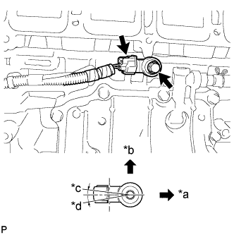 |
Install the sensor with the bolt so that the sensor is angled as shown in the illustration.
| *a | Front of Engine |
| *b | Up |
| *c | 7° |
| *d | 10° |
Connect the sensor connector.
| 5. INSTALL SENSOR WIRE |
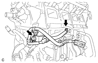 |
Install the sensor wire with the bolt.
Connect the knock control sensor connector.
| 6. INSTALL INTAKE MANIFOLD |
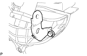 |
Install the wire harness clamp bracket with the bolt.
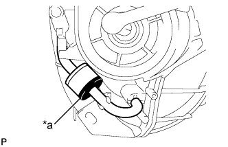 |
Connect the 2 vacuum hoses and check that the No. 1 check valve is installed as shown in the illustration.
| *a | Black |
Check the tumble control valves (w/ TCV).
Install a new intake manifold gasket to the intake manifold.
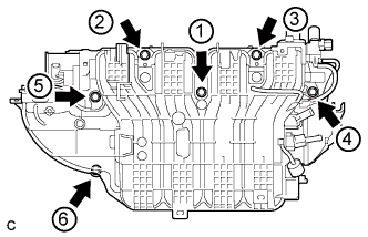 |
Install the intake manifold by tightening the 6 bolts in the sequence shown in the illustration (w/ TCV).
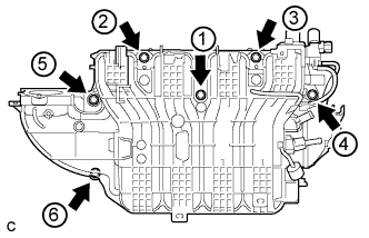 |
Install the intake manifold by tightening the 6 bolts in the sequence shown in the illustration (w/o TCV).
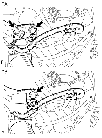 |
Connect the intake air control actuator connector and 2 wire harness clamps (w/ TCV).
Connect the 2 wire harness clamps (w/o TCV).
Install the wire harness clamp with the bolt.
| *A | w/ TCV |
| *B | w/o TCV |
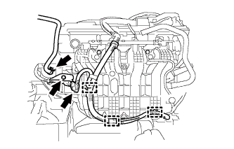 |
Install the wire harness clamp bracket with the bolt.
Connect the 3 wire harness clamps and connector.
Connect the fuel vapor feed hose.
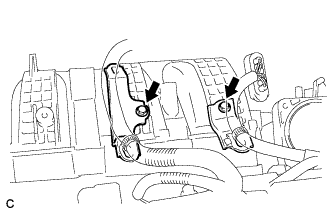 |
Install the 2 wire harness clamp brackets with the 2 bolts.
| 7. INSTALL FUEL DELIVERY PIPE SUB-ASSEMBLY |
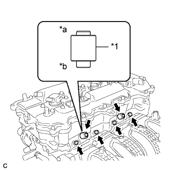 |
Install 4 new injector vibration insulators to the cylinder head.
| *1 | Fuel Delivery Spacer |
| *a | Fuel Delivery Pipe Side |
| *b | Cylinder Head Side |
Install the 2 fuel delivery spacers onto the cylinder head.
Install the fuel delivery pipe sub-assembly with the 4 fuel injector assemblies and install the 2 bolts.
| 8. INSTALL UNION TO CONNECTOR TUBE HOSE (for LHD) |
Connect the union to connector tube hose to the intake manifold.
| 9. INSTALL UNION TO CHECK VALVE HOSE (for RHD) |
Connect the union to connector tube hose to the intake manifold.
| 10. CONNECT NO. 2 VENTILATION HOSE |
Connect the No. 2 ventilation hose to the intake manifold.
| 11. INSTALL VACUUM SWITCHING VALVE ASSEMBLY (for ACIS) |
Install the vacuum switching valve assembly with the bolt.
Connect the 2 vacuum hoses and connector.
Connect the union to connector tube hose and wire harness clamp.
| 12. INSTALL WATER BY-PASS HOSE |
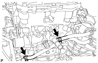 |
Install the No. 1 and No. 2 water by-pass hoses.
| 13. INSTALL THROTTLE WITH MOTOR BODY ASSEMBLY |
Install a new gasket to the intake manifold.
Install the fuel tube bracket with the bolt.
Install the throttle with motor body assembly with the 4 bolts.
Connect the throttle body connector.
Connect the fuel tube to the clamp.
Connect the No. 2 water by-pass hose to the throttle with motor body assembly.
Connect the water by-pass hose to the throttle with motor body assembly.
| 14. INSTALL NO. 1 COMPRESSOR MOUNTING BRACKET |
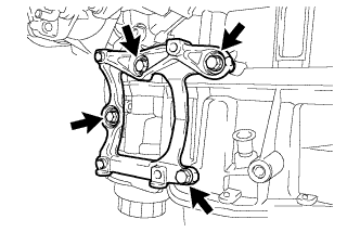 |
Install the bracket with the 4 bolts.
| 15. INSTALL EXHAUST MANIFOLD CONVERTER SUB-ASSEMBLY |
Install a new exhaust manifold to head gasket onto the cylinder head.
Temporarily install the exhaust manifold converter sub-assembly with the 5 nuts.
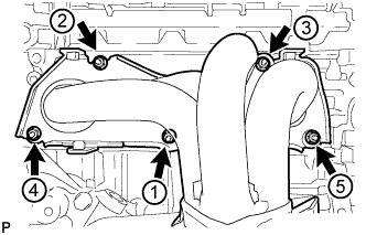 |
Tighten the 5 nuts in the sequence shown in the illustration.
| 16. INSTALL NO. 1 EXHAUST MANIFOLD HEAT INSULATOR |
Install the No. 1 exhaust manifold heat insulator with the 4 bolts.
| 17. INSTALL NO. 2 MANIFOLD STAY |
Install the No. 2 manifold stay with the bolt and nut.
| 18. INSTALL MANIFOLD STAY |
Install the manifold stay with the bolt and nut.
| 19. INSTALL ENGINE OIL LEVEL DIPSTICK GUIDE |
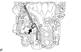 |
Apply a light coat of engine oil to a new O-ring.
Install the O-ring to the engine oil level dipstick guide.
Install the engine oil level dipstick guide with the bolt.
Install the engine oil level dipstick.
| 20. INSTALL ENGINE HANGERS |
Install the 2 engine hangers with the 4 bolts as shown in the illustration.
| Item | Part No. |
| No. 1 engine hanger | 12281-36020 |
| No. 2 engine hanger | 12282-36021 |
| Bolt | 91552-81040 or 91552-81025 |
Attach an engine sling device and hang the engine with the chain block.