 |
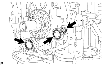
Apply a light coat of engine oil to 3 new gaskets.
OIL PUMP > INSTALLATION |
| 1. INSTALL TIMING CHAIN COVER SUB-ASSEMBLY |
|
Apply a light coat of engine oil to 3 new gaskets.
Install the 3 gaskets to the stiffening crankcase.
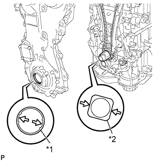 |
Align the drive rotor spline and the crankshaft timing sprocket as shown in the illustration.
| *1 | Drive Rotor Spline |
| *2 | Crankshaft Timing Sprocket |
Apply seal packing in a line to the timing chain cover as shown in the following illustration.
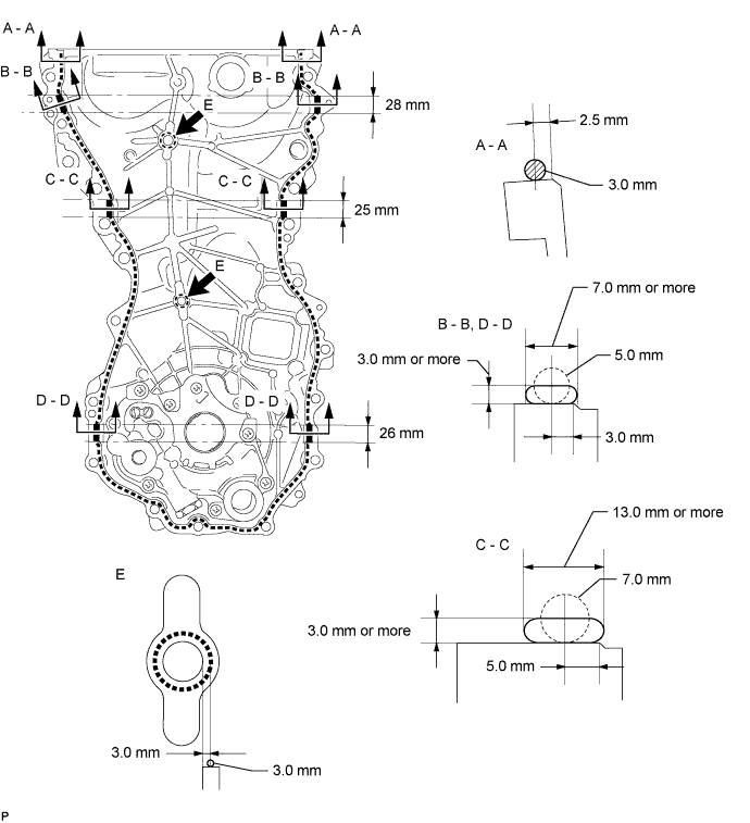
| Area | Seal Packing Diameter (Round) | Distance from Edge of Cover to Center of Seal Packing | Seal Packing Application Length |
| Seal Pacing Dimension (Flat) | |||
| Dashed Line | 3.0 mm (0.118 in.) | 2.5 mm (0.0984 in.) | - |
| - | |||
| A - A | 3.0 mm (0.118 in.) | 2.5 mm (0.0984 in.) | - |
| - | |||
| B - B | 5.0 mm (0.197 in.) | 3.0 mm (0.118 in.) | 28 mm (1.10 in.) |
| 7.0 mm (0.276 in.) or more wide and 3.0 mm (0.118 in.) or more thick | |||
| C - C | 7.0 mm (0.276 in.) | 5.0 mm (0.197 in.) | 25 mm (0.984 in.) |
| 13.0 mm (0.512 in.) or more wide and 3.0 mm (0.118 in.) or more thick | |||
| D - D | 5.0 mm (0.197 in.) | 3.0 mm (0.118 in.) | 26 mm (1.02 in.) |
| 7.0 mm (0.276 in.) or more wide and 3.0 mm (0.118 in.) or more thick | |||
| E | 3.0 mm (0.118 in.) | 3.0 mm (0.118 in.) | - |
| - |
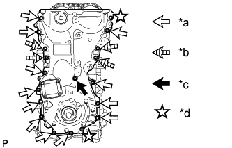 |
Temporarily install the timing chain cover with the 17 bolts and 2 nuts.
| *a | Bolt A |
| *b | Bolt B |
| *c | Bolt C |
| *d | Nut |
| Item | Length | Thread Diameter |
| Bolt A | 30 mm (1.18 in.) | 8 mm (0.315 in.) |
| Bolt B | 35 mm (1.38 in.) | 10 mm (0.394 in.) |
| Bolt C | 45 mm (1.77 in.) | 8 mm (0.315 in.) |
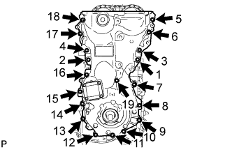 |
Tighten the 17 bolts and 2 nuts in several steps, in the sequence shown in the illustration.
| 2. INSTALL ENGINE MOUNTING BRACKET RH |
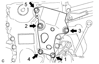 |
Install the engine mounting bracket RH with the 5 bolts in the order shown in the illustration.
| 3. INSTALL TIMING CHAIN COVER OIL SEAL |
Apply MP grease to the lip of a new oil seal.
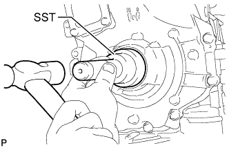 |
Using SST and a hammer, tap in the oil seal until its surface is flush with the timing chain cover edge.
| 4. INSTALL CRANKSHAFT PULLEY |
Align the pulley set key with the key groove of the crankshaft pulley.
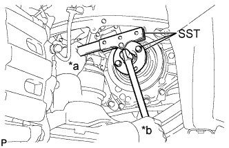 |
Using SST, hold the crankshaft pulley and install the pulley bolt.
| *a | Hold |
| *b | Turn |
| 5. INSTALL CRANKSHAFT POSITION SENSOR |
Clean and degrease the threads of the bolt for the crankshaft position sensor.
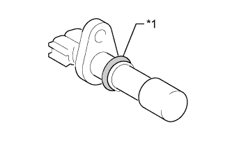 |
Apply a light coat of engine oil to the O-ring of the sensor.
| *1 | O-ring |
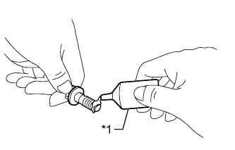 |
Apply adhesive to 2 or 3 threads of the bolt.
| *1 | Adhesive |
Install the sensor with the bolt.
Connect the sensor connector.
| 6. INSTALL V-RIBBED BELT TENSIONER ASSEMBLY |
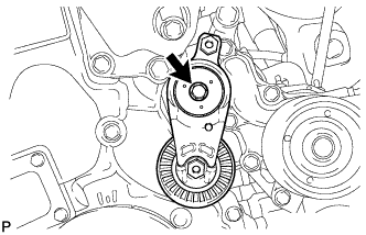 |
Install the V-ribbed belt tensioner with the bolt.
| 7. INSTALL CYLINDER HEAD COVER SUB-ASSEMBLY |
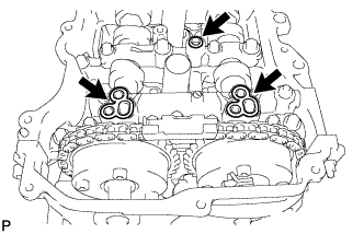 |
Apply a light coat of engine oil to 3 new gaskets.
Install the 3 gaskets to the camshaft bearing caps.
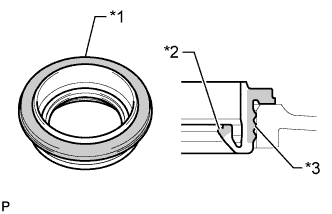 |
Visually check the spark plug tube gasket.
| Area | Specified Condition |
| Upper surface | No scratches or deformation |
| Outer lip | No scratches or deformation |
| Inner lip | No scratches |
| *1 | Upper Surface |
| *2 | Inner Lip |
| *3 | Outer Lip |
Install a new gasket to the cylinder head cover.
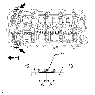 |
Apply seal packing as shown in the illustration.
| *1 | Seal packing |
| *2 | Timing Chain Cover |
| *3 | Camshaft Housing |
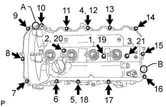 |
Align the cylinder head cover with pin A. Then align the cylinder head cover with pin B and install the cylinder head cover.
Install 3 new seal washers and the 16 bolts, and then tighten the bolts in the order shown in the illustration.
| 8. INSTALL IGNITION COIL ASSEMBLY |
Install the 4 ignition coil assemblies with the 4 bolts.
Connect the 4 ignition coil assembly connectors.
| 9. INSTALL ENGINE WIRE |
| 10. INSTALL ENGINE AND TRANSAXLE |