Before connecting the connector, check that the position of the white housing lock is correct as shown in the illustration.
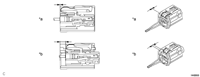
| *a | Incorrect | *b | Correct |
SIDE AIRBAG SENSOR (for Front Side) > INSTALLATION |
| 1. INSTALL DOOR SIDE AIRBAG SENSOR |
Check that the ignition switch is off.
Check that the cable is disconnected from the negative (-) battery terminal.
Before connecting the connector, check that the position of the white housing lock is correct as shown in the illustration.
| *a | Incorrect | *b | Correct |
Insert the pin (stopper) into the door hole and install the door side airbag sensor to the front door panel with the bolt.
Connect the connector to the door side airbag sensor.
Be sure to engage the connectors until they are locked (when locking, make sure that a click sound can be heard).
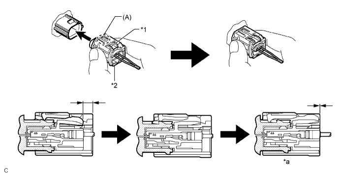
| *1 | White Housing Lock | *2 | Yellow CPA |
| *a | Connection is Completed | - | - |
Check that there is no looseness in the installation parts of the door side airbag sensor.
| 2. INSTALL FRONT DOOR TRIM BOARD SUB-ASSEMBLY |
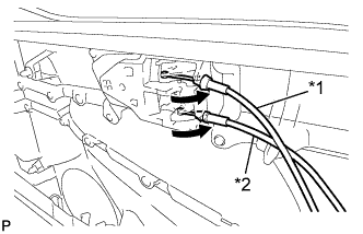 |
Connect the front door lock remote control cable assembly and front door inside locking cable assembly.
| *1 | Front Door Inside Locking Cable Assembly |
| *2 | Front Door Lock Remote Control Cable Assembly |
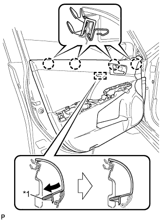 |
Engage the front door trim board sub-assembly with the 4 claws and reference boss as shown in the illustration.
| *1 | Reference Boss |
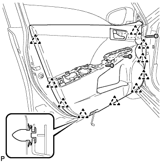 |
Engage the 10 clips and install to front door trim board sub-assembly.
Install the 3 screws.
If protective tape has been applied, remove it.
| 3. INSTALL COURTESY LIGHT ASSEMBLY |
Connect the connector.
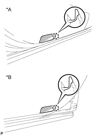 |
Engage the claw to install the courtesy light assembly.
| *A | for LH Side |
| *B | for RH Side |
| 4. INSTALL FRONT DOOR ARMREST ASSEMBLY |
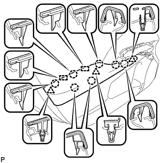 |
Engage the 2 guides, 3 clips and 7 claws, and install the front armrest assembly.
| 5. INSTALL POWER WINDOW REGULATOR MASTER SWITCH ASSEMBLY WITH FRONT DOOR ARMREST BASE PANEL (for Driver Side) |
Connect each connector.
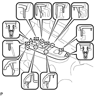 |
Engage the 4 guides, 2 clips and 5 claws, and install the power window regulator master switch assembly with front door armrest base panel.
| 6. INSTALL POWER WINDOW REGULATOR SWITCH ASSEMBLY WITH FRONT DOOR ARMREST BASE PANEL (for Front Passenger Side) |
Connect each connector.
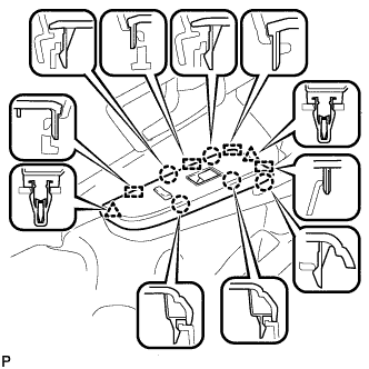 |
Engage the 4 guides, 2 clips and 5 claws, and install the power window regulator switch assembly with front door armrest base panel.
| 7. INSTALL FRONT DOOR LOWER FRAME BRACKET GARNISH |
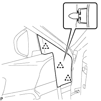 |
Engage the 3 clips to install the front door lower frame bracket garnish.
| 8. INSTALL FRONT DOOR INSIDE HANDLE BEZEL PLUG |
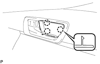 |
Engage the 3 claws to install the front door inside handle bezel plug.
| 9. CONNECT CABLE TO NEGATIVE BATTERY TERMINAL |
| 10. PERFORM DIAGNOSTIC SYSTEM CHECK |
| 11. INSPECT SRS WARNING LIGHT |