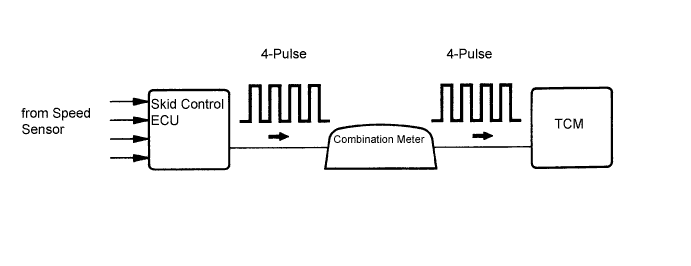
DTC P0500 Vehicle Speed Sensor "A" |
| DTC No. | DTC Detection Condition | Trouble Area |
| P0500 | When the ECT sensor is normal and the counter gear speed is 300 rpm or more, the vehicle speed signal is not input for 2 seconds or more. |
|
| Related DTCs | P0500: Vehicle Speed Sensor Circuit |
| Required sensors/components (Main) | Vehicle speed sensor, Combination meter, ABS ECU |
| Required sensors/components (Sub) | Counter gear Speed (CS) sensor, ECT sensor |
| Frequency of operation | Continuous |
| Duration | 2 seconds |
| MIL operation | Immediately |
| Sequence operation | None |
| Engine | Running |
| Transmission counter gear revolution | 300 rpm or more |
| Battery voltage | 8 V or more |
| Engine switch | on (IG) |
| Starter | OFF |
| Either a or b is met (See below) | |
| a. All of the following conditions are met | |
| ECT | 20°C (68°F) or more |
| ECT sensor fail | Not detected |
| Time after PNP switch ON to OFF | 2 sec. or more |
| b. All of the following conditions are met | |
| ECT | Less than 20°C (68°F) |
| ECT sensor fail | Detected |
| Time after PNP switch ON to OFF | 30 sec. or more |
| Vehicle speed sensor signal | No pulse input |
| 1.READ VALUE USING TECHSTREAM (VEHICLE SPEED) |
Drive the vehicle and check whether the operation of the speedometer in the combination meter assembly is normal.
Connect the Techstream to the DLC3.
Turn the engine switch on (IG).
Turn the Techstream on.
Enter the following menus: Powertrain / ECT / Data List / Vehicle Speed.
Drive the vehicle.
Read the value displayed on the Techstream.
|
| ||||
| OK | ||
 | ||
| ||
| 2.CHECK COMBINATION METER ASSEMBLY (SPD SIGNAL WAVEFORM) |
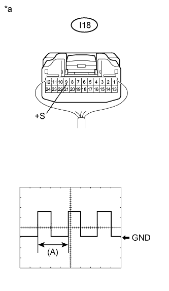 |
Inspect the combination meter assembly using an oscilloscope.
Move the shift lever to N.
Jack up the vehicle.
Turn the engine switch on (IG).
Measure the voltage between the terminal of the combination meter assembly and the body ground while the wheel is turned slowly.
| Tester Connection | Switch Condition | Specified Condition |
| I18-9 (+S) - Body ground | Engine switch on (IG) | Voltage generated intermittently |
| *a | Component with harness connected (Combination Meter Assembly) |
|
| ||||
| OK | |
 |
| 3.CHECK HARNESS AND CONNECTOR (COMBINATION METER ASSEMBLY - TCM) |
Disconnect the combination meter assembly connector.
Disconnect the TCM connector.
Measure the resistance according to the value(s) in the table below.
| Tester Connection | Condition | Specified Condition |
| I18-9 (+S) - E7-3 (SPD) | Always | Below 1 Ω |
Reconnect the combination meter assembly connector.
Reconnect the TCM connector.
|
| ||||
| OK | ||
| ||
| ||

