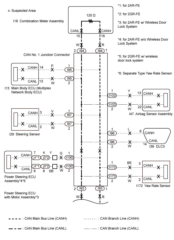
CAN COMMUNICATION SYSTEM > Check CAN Bus Line for Short to GND |
| Symptom | Trouble Area |
| No resistance exists between terminals 6 (CANH) and 4 (CG) or 14 (CANL) and 4 (CG) of DLC3. |
|
| 1.CHECK FOR SHORT TO GND IN CAN BUS LINE (DLC3 BRANCH LINE) |
Disconnect the cable from the negative (-) battery terminal.
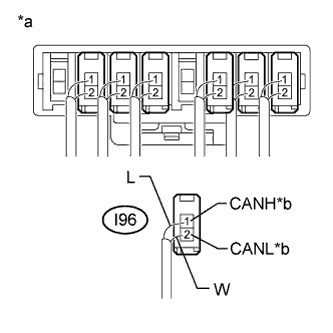 |
Disconnect the DLC3 branch line connector (I96) from the CAN No. 1 junction connector.
| *a | Rear view of wire harness connector (to CAN No. 1 Junction Connector) |
| *b | to DLC3 |
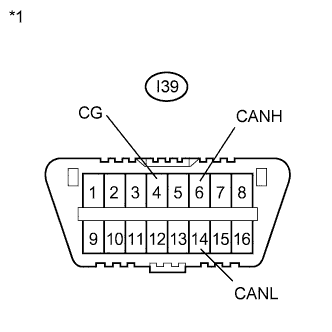 |
Measure the resistance according to the value(s) in the table below.
| Tester Connection | Condition | Specified Condition |
| I39-6 (CANH) - I39-4 (CG) | Cable disconnected from negative (-) battery terminal | 200 Ω or higher |
| I39-14 (CANL) - I39-4 (CG) | Cable disconnected from negative (-) battery terminal | 200 Ω or higher |
| *1 | DLC3 |
|
| ||||
| OK | |
 |
| 2.CHECK FOR SHORT TO GND IN CAN BUS LINE |
Reconnect the DLC3 branch line connector (I96) to the CAN No. 1 junction connector.
|
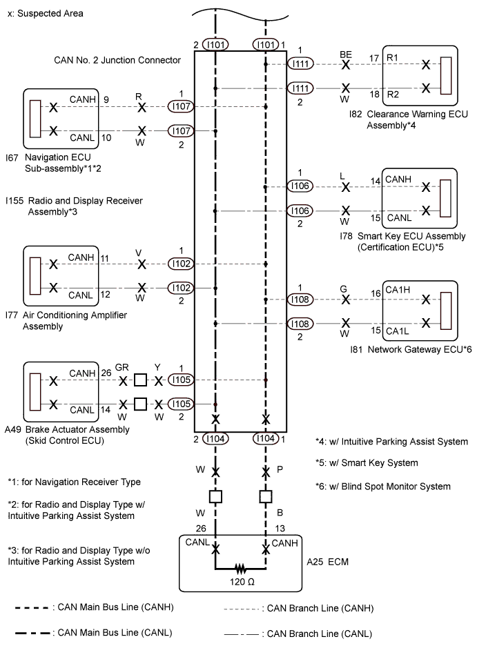
Disconnect the connectors from the CAN No. 1 junction connector or CAN No. 2 junction connector one at a time.
| *1 | DLC3 |
Using an ohmmeter, measure the resistance between terminals 6 (CANH) and 4 (CG), and between terminals 14 (CANL) and 4 (CG) of the DLC3 each time a connector is disconnected.
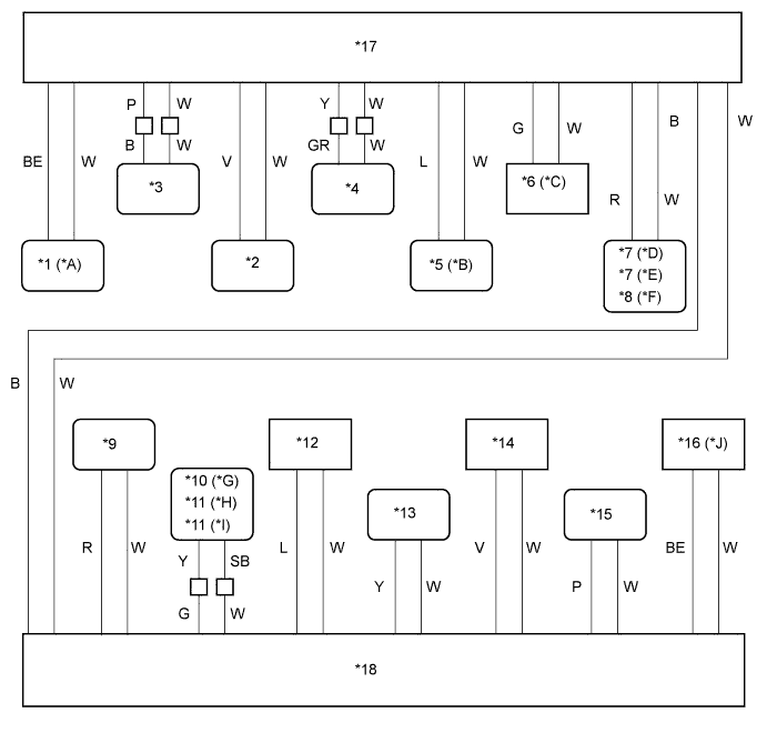
| *A | w/ Intuitive Parking Assist System | *B | w/ Smart Key System |
| *C | w/ Blind Spot Monitor System | *D | for Navigation Receiver Type |
| *E | for Radio and Display Type w/ Intuitive Parking Assist System | *F | for Radio and Display Type w/o Intuitive Parking Assist System |
| *G | for 2AR-FE w/ Wireless Door Lock System | *H | for 2AR-FE w/o Wireless Door Lock System |
| *I | for 2GR-FE w/ Wireless Door Lock System | *J | Separate Type Yaw Rate Sensor |
| *1 | Clearance Warning ECU Assembly | *2 | Air Conditioning Amplifier Assembly |
| *3 | ECM | *4 | Brake Actuator Assembly |
| *5 | Smart Key ECU Assembly (Certification ECU) | *6 | Network Gateway ECU |
| *7 | Navigation ECU Sub-assembly | *8 | Radio and Display Receiver Assembly |
| *9 | Combination Meter Assembly | *10 | Power Steering ECU with Motor Assembly |
| *11 | Power Steering ECU Assembly | *12 | DLC3 |
| *13 | Airbag Sensor Assembly | *14 | Steering Sensor |
| *15 | Main Body ECU (Multiplex Network Body ECU) | *16 | Yaw Rate Sensor |
| *17 | CAN No. 2 Junction Connector | *18 | CAN No. 1 Junction Connector |
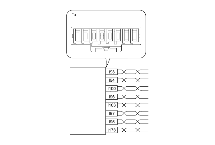
| *a | Component without harness connected (CAN No. 1 Junction Connector) | - | - |
| CAN No. 1 Junction Connector Side | Code | Color (CANH Side) | Color (CANL Side) |
| Yaw rate sensor*4 | I173 | BE | W |
| Main body ECU (Multiplex network body ECU) | I95 | P | W |
| Steering sensor | I97 | V | W |
| Airbag sensor assembly | I103 | Y | W |
| DLC3 | I96 | L | W |
| I100 | G | W |
| Combination meter assembly | I94 | R | W |
| CAN main bus line (bus line connecting CAN No. 1 junction connector and CAN No. 2 junction connector) | I93 | B | W |
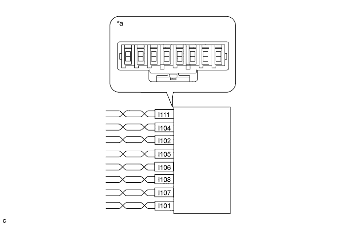
| *a | Component without harness connected (CAN No. 2 Junction Connector) | - | - |
| CAN No. 2 Junction Connector Side | Code | Color (CANH Side) | Color (CANL Side) |
| CAN main bus line (bus line connecting CAN No. 1 junction connector and CAN No. 2 junction connector) | I101 | B | W |
| I107 | R | W |
| Network Gateway ECU*4 | I108 | G | W |
| Smart key ECU assembly (Certification ECU)*5 | I106 | L | W |
| Brake actuator assembly (Skid control ECU) | I105 | Y | W |
| Air conditioning amplifier assembly | I102 | V | W |
| ECM | I104 | P | W |
| Clearance warning ECU assembly*6 | I111 | BE | W |
| Symptom | Proceed to |
| The resistance between terminals 6 (CANH) and 4 (CG), or the resistance between 14 (CANL) and 4 (CG) is still below 200 Ω when all the specified connectors are disconnected from the CAN junction connector. (There is a short to GND in the CAN main bus lines between the CAN No. 1 junction connector and CAN No. 2 junction connector.) | A |
| The resistance between terminals 6 (CANH) and 4 (CG), or the resistance between 14 (CANL) and 4 (CG) becomes normal (200 Ω or more) when a connector is disconnected from the CAN junction connector. (There is a short to GND in one of the areas that relate to the disconnected bus lines.) | B |
When there is a short to GND in one or more of the bus lines that connect to an ECU (or sensor):
Reconnect all of the connectors to the CAN junction connector, except for the one that was disconnected last (the bus line that is shorted to GND). Check that the resistance shown on the tester is normal (200 Ω or more) to confirm that there is a short to GND in the one branch line only.
When there is no short to GND in any of the bus lines that connect to the ECUs and sensors:
With all the specified connectors for ECUs and sensors disconnected, proceed with the inspection of the CAN bus main lines between the CAN No. 1 junction connector and CAN No. 2 junction connector.
|
| ||||
| A | |
|
| 3.CHECK CAN NO. 1 JUNCTION CONNECTOR |
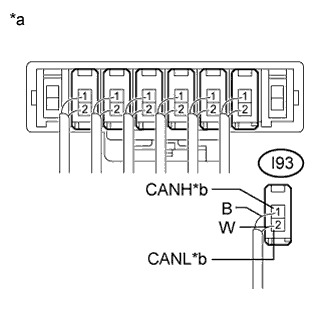 |
Disconnect the CAN main bus line connector (I93) from the CAN No. 1 junction connector.
| *a | Rear view of wire harness connector (to CAN No. 1 Junction Connector) |
| *b | (to CAN No. 2 Junction Connector) |
|
Measure the resistance according to the value(s) in the table below.
| Tester Connection | Condition | Specified Condition |
| I39-6 (CANH) - I39-4 (CG) | Cable disconnected from negative (-) battery terminal | 200 Ω or higher |
| I39-14 (CANL) - I39-4 (CG) | Cable disconnected from negative (-) battery terminal | 200 Ω or higher |
| *1 | DLC3 |
|
| ||||
| OK | |
|
| 4.CHECK CAN NO. 2 JUNCTION CONNECTOR (CAN NO. 1 J/C - CAN NO. 2 J/C) |
Reconnect the CAN main bus line connector (I93) to the CAN No. 1 junction connector.
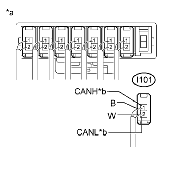 |
Disconnect the CAN main bus line connector (I101) from the CAN No. 2 junction connector.
| *a | Rear view of wire harness connector (to CAN No. 2 Junction Connector) |
| *b | (to CAN No. 1 Junction Connector) |
|
Measure the resistance according to the value(s) in the table below.
| Tester Connection | Condition | Specified Condition |
| I39-6 (CANH) - I39-4 (CG) | Cable disconnected from negative (-) battery terminal | 200 Ω or higher |
| I39-14 (CANL) - I39-4 (CG) | Cable disconnected from negative (-) battery terminal | 200 Ω or higher |
| *1 | DLC3 |
|
| ||||
| OK | ||
 | ||
| ||
| 5.CHECK FOR SHORT TO GND IN CAN BUS LINE (ECU, SENSOR) |
Reconnect the connector of the bus line that is shorted to GND to the CAN junction connector (the connector that caused the bus line resistance to change to 200 Ω or more when it was disconnected).
|
Disconnect the connector that includes the DLC3 connected CAN lines (such as CANH and CANL) from the ECU (or sensor) to which the bus line shorted to GND is connected (Click here).
| *1 | DLC3 |
Measure the resistance according to the value(s) in the table below.
| Tester Connection | Condition | Specified Condition |
| I39-6 (CANH) - I39-4 (CG) | Cable disconnected from negative (-) battery terminal | 200 Ω or higher |
| I39-14 (CANL) - I39-4 (CG) | Cable disconnected from negative (-) battery terminal | 200 Ω or higher |
|
| ||||
| OK | ||
| ||
| ||

