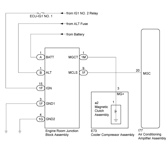
AIR CONDITIONING SYSTEM (for Automatic Air Conditioning System) > Air Conditioning Compressor Magnetic Clutch Circuit |
| 1.CHECK ENGINE ROOM JUNCTION BLOCK ASSEMBLY |
Using a voltmeter, check the signal reading of the engine room junction block assembly (Click here).
|
| ||||
| OK | |
 |
| 2.CHECK HARNESS AND CONNECTOR (ENGINE ROOM JUNCTION BLOCK ASSEMBLY POWER SOURCE AND BODY GROUND) |
Remove the engine room junction block assembly from the engine room relay block and junction block assembly (Click here).
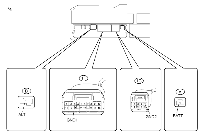
| *a | Component without engine room junction block assembly (Engine Room Junction Block Assembly) | - | - |
Measure the voltage according to the value(s) in the table below.
| Tester Connection | Condition | Specified Condition |
| A-1 (BATT) - Body ground | Always | 11 to 14 V |
| B-1 (ALT) - Body ground | Always | 11 to 14 V |
Measure the resistance according to the value(s) in the table below.
| Tester Connection | Condition | Specified Condition |
| 1F-3 (GND1) - Body ground | Always | Below 1 Ω |
| 1G-4 (GND2) - Body ground | Always | Below 1 Ω |
|
| ||||
| OK | |
|
| 3.CHECK HARNESS AND CONNECTOR (ENGINE ROOM JUNCTION BLOCK ASSEMBLY - MAGNETIC CLUTCH ASSEMBLY) |
Disconnect the E73 cooler compressor assembly connector.
Measure the resistance according to the value(s) in the table below.
| Tester Connection | Condition | Specified Condition |
| 1M-1 (MGCT) - E73-3 (MG+) | Always | Below 1 Ω |
|
| ||||
| OK | |
|
| 4.INSPECT COOLER COMPRESSOR ASSEMBLY |
Remove the engine room junction block assembly.
Disconnect the a2 magnetic clutch assembly connector.
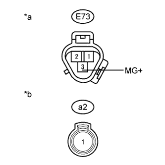 |
Measure the resistance according to the value(s) in the table below.
| Tester Connection | Condition | Specified Condition |
| E73-3 (MG+) - a2-1 | Always | Below 1 Ω |
| E73-3 (MG+) - Body ground | Always | 10 kΩ or higher |
| *a | Component without harness connected (Cooler Compressor Assembly) |
| *b | Component without harness connected (Magnetic Clutch Assembly) |
|
| ||||
| OK | |
|
| 5.INSPECT ENGINE ROOM JUNCTION BLOCK ASSEMBLY |
Disconnect the I77 air conditioning amplifier assembly connector.
Reconnect the engine room junction block assembly connector.
Measure the voltage according to the value(s) in the table below.
| Tester Connection | Condition | Specified Condition |
| I77-20 (MGC) - Body ground | Ignition switch off | Below 1 V |
| I77-20 (MGC) - Body ground | Ignition switch ON | 11 to 14 V |
|
| ||||
| OK | |
|
| 6.INSPECT AIR CONDITIONING AMPLIFIER ASSEMBLY |
Reconnect the I77 air conditioning amplifier assembly connector.
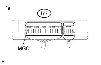 |
Measure the voltage and voltage according to the value(s) in the table below.
| Tester Connection | Condition | Specified Condition |
| I77-20 (MGC) - Body ground | Ignition switch ON A/C switch: off | 11 to 14 V |
| I77-20 (MGC) - Body ground | Ignition switch off A/C switch: on | Below 1 V |
| *a | Component with harness connected (Air Conditioning Amplifier Assembly) |
|
| ||||
| OK | ||
 | ||
| ||
| 7.CHECK HARNESS AND CONNECTOR (AIR CONDITIONING AMPLIFIER ASSEMBLY - ENGINE ROOM JUNCTION BLOCK ASSEMBLY) |
Measure the voltage and resistance according to the value(s) in the table below.
| Tester Connection | Condition | Specified Condition |
| I77-20 (MGC) - 1F-9 (MCLS) | Always | Below 1 Ω |
| I77-20 (MGC) - Body ground | Always | 10 kΩ or higher |
|
| ||||
| OK | ||
| ||
| ||

