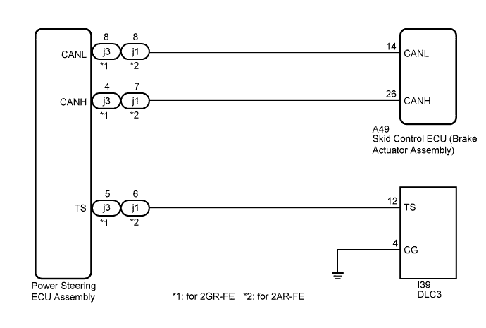
VEHICLE STABILITY CONTROL SYSTEM > TS and CG Terminal Circuit |
| 1.CHECK CAN COMMUNICATION SYSTEM |
Check if a CAN communication system DTC is output (Click here).
| Result | Proceed to |
| DTC is not output. | A |
| DTC is output. | B |
|
| ||||
| A | |
 |
| 2.INSPECT DLC3 |
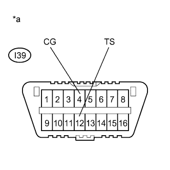 |
Turn the ignition switch to ON.
Measure the voltage according to the value(s) in the table below.
| Tester Connection | Condition | Specified Condition |
| I39-12 (TS) - I39-4 (CG) | Ignition switch ON | 11 to 14 V |
| *a | Front view of DLC3 |
|
| ||||
| OK | |
|
| 3.CHECK POWER STEERING ECU ASSEMBLY (TS of DLC3 INPUT) |
|
Turn the ignition switch off.
Using SST, connect terminals TS and CG of the DLC3.
Check that the P/S warning light is blinking.
| *a | Front view of DLC3 |
|
| ||||
| OK | ||
 | ||
| ||
| 4.CHECK HARNESS AND CONNECTOR (TS of DLC3 - POWER STEERING ECU ASSEMBLY) |
Turn the ignition switch off.
Disconnect the power steering ECU assembly connector.
Measure the resistance according to the value(s) in the table below.
| Tester Connection | Condition | Specified Condition |
| I39-12 (TS) - j3-5 (TS) | Always | Below 1 Ω |
| I39-12 (TS) - Body ground | Always | 10 kΩ or higher |
| Tester Connection | Condition | Specified Condition |
| I39-12 (TS) - j1-6 (TS) | Always | Below 1 Ω |
| I39-12 (TS) - Body ground | Always | 10 kΩ or higher |
|
| ||||
| OK | |
|
| 5.CHECK HARNESS AND CONNECTOR (CG of DLC3 - BODY GROUND) |
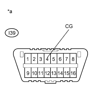 |
Measure the resistance according to the value(s) in the table below.
| Tester Connection | Condition | Specified Condition |
| I39-4 (CG) - Body ground | Always | Below 1 Ω |
| *a | Front view of DLC3 |
|
| ||||
| OK | |
|
| 6.CHECK POWER STEERING ECU ASSEMBLY (TS of DLC3 INPUT) |
|
Reconnect the power steering ECU assembly connector.
Using SST, connect terminals TS and CG of the DLC3.
Check that the P/S warning light is blinking.
| *a | Front view of DLC3 |
|
| ||||
| OK | ||
| ||
| ||

