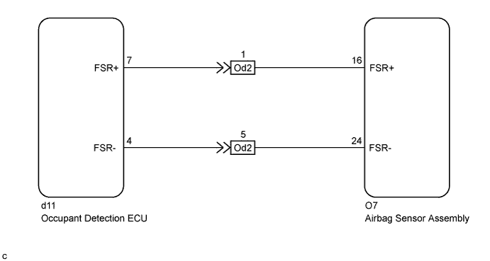
DTC B1650/32 Occupant Classification System Malfunction |
| DTC No. | DTC Detection Condition | Trouble Area |
| B1650/32 |
|
|
| 1.CHECK DTC (OCCUPANT DETECTION ECU) |
Check for DTCs of the occupant detection ECU (Click here).
|
| ||||
| OK | |
 |
| 2.CHECK CONNECTORS |
Turn the ignition switch off.
Disconnect the cable from the negative (-) battery terminal.
Check that the connectors are properly connected to the airbag sensor assembly and occupant detection ECU. Also check that the connectors that link the No. 2 floor wire and front seat wire RH are properly connected.
Disconnect the connectors from the airbag sensor assembly and occupant detection ECU. Also disconnect the connectors that link the No. 2 floor wire and front seat wire RH.
Check that the terminals of the connectors are not damaged.
|
| ||||
| OK | |
|
| 3.CHECK OCCUPANT CLASSIFICATION SYSTEM CIRCUIT (OPEN) |
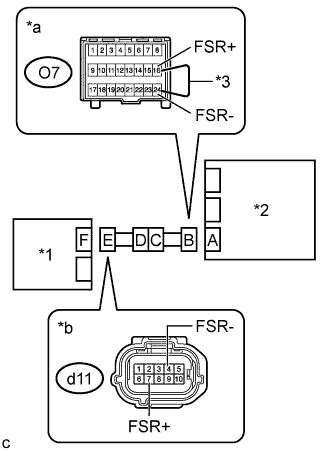 |
Connect the connectors that link the No. 2 floor wire and front seat wire RH.
Using a service wire, connect terminals 16 (FSR+) and 24 (FSR-) of connector B.
Measure the resistance according to the value(s) in the table below.
| Tester Connection | Condition | Specified Condition |
| d11-7 (FSR+) - d11-4 (FSR-) | Always | Below 1 Ω |
| *1 | Occupant Detection ECU |
| *2 | Airbag Sensor Assembly |
| *3 | Service Wire |
| *a | Front view of wire harness connector (to Airbag Sensor Assembly) |
| *b | Front view of wire harness connector (to Occupant Detection ECU) |
|
| ||||
| OK | |
|
| 4.CHECK OCCUPANT CLASSIFICATION SYSTEM CIRCUIT (SHORT) |
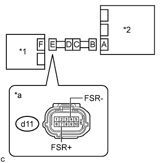 |
Disconnect the service wire from connector B.
Measure the resistance according to the value(s) in the table below.
| Tester Connection | Condition | Specified Condition |
| d11-7 (FSR+) - d11-4 (FSR-) | Always | 1 MΩ or higher |
| *1 | Occupant Detection ECU |
| *2 | Airbag Sensor Assembly |
| *a | Front view of wire harness connector (to Occupant Detection ECU) |
|
| ||||
| OK | |
|
| 5.CHECK OCCUPANT CLASSIFICATION SYSTEM CIRCUIT (SHORT TO B+) |
|
Connect the cable to the negative (-) battery terminal.
Turn the ignition switch to ON.
Measure the voltage according to the value(s) in the table below.
| Tester Connection | Condition | Specified Condition |
| d11-7 (FSR+) - Body ground | Ignition switch ON | Below 1 V |
| d11-4 (FSR-) - Body ground | Ignition switch ON | Below 1 V |
Turn the ignition switch off.
Disconnect the cable from the negative (-) battery terminal.
| *1 | Occupant Detection ECU |
| *2 | Airbag Sensor Assembly |
| *a | Front view of wire harness connector (to Occupant Detection ECU) |
|
| ||||
| OK | |
|
| 6.CHECK OCCUPANT CLASSIFICATION SYSTEM CIRCUIT (SHORT TO GROUND) |
|
Measure the resistance according to the value(s) in the table below.
| Tester Connection | Condition | Specified Condition |
| d11-7 (FSR+) - Body ground | Always | 1 MΩ or higher |
| d11-4 (FSR-) - Body ground | Always | 1 MΩ or higher |
| *1 | Occupant Detection ECU |
| *2 | Airbag Sensor Assembly |
| *a | Front view of wire harness connector (to Occupant Detection ECU) |
|
| ||||
| OK | ||
 | ||
| ||
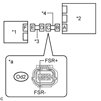
| 7.CHECK NO. 2 FLOOR WIRE (OPEN) |
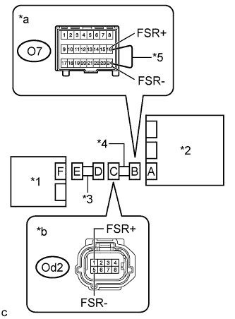 |
Disconnect the front seat wire RH from the No. 2 floor wire.
Measure the resistance according to the value(s) in the table below.
| Tester Connection | Condition | Specified Condition |
| Od2-1 (FSR+) - Od2-5 (FSR-) | Always | Below 1 Ω |
Disconnect the service wire from connector B.
| *1 | Occupant Detection ECU |
| *2 | Airbag Sensor Assembly |
| *3 | Front Seat Wire RH |
| *4 | No. 2 Floor Wire |
| *5 | Service Wire |
| *a | Front view of wire harness connector (to Airbag Sensor Assembly) |
| *b | Front view of wire harness connector (to Front Seat Wire RH) |
|
| ||||
| OK | ||
| ||
| ||
| 8.CHECK NO. 2 FLOOR WIRE (SHORT) |
 |
Disconnect the front seat wire RH from the No. 2 floor wire.
Measure the resistance according to the value(s) in the table below.
| Tester Connection | Condition | Specified Condition |
| Od2-1 (FSR+) - Od2-5 (FSR-) | Always | 1 MΩ or higher |
| *1 | Occupant Detection ECU |
| *2 | Airbag Sensor Assembly |
| *3 | Front Seat Wire RH |
| *4 | No. 2 Floor Wire |
| *a | Front view of wire harness connector (to Front Seat Wire RH) |
|
| ||||
| OK | ||
| ||
| ||
| 9.CHECK NO. 2 FLOOR WIRE (SHORT TO B+) |
|
Disconnect the front seat wire RH from the No. 2 floor wire.
Connect the cable to the negative (-) battery terminal.
Turn the ignition switch to ON.
Measure the voltage according to the value(s) in the table below.
| Tester Connection | Condition | Specified Condition |
| Od2-1 (FSR+) - Body ground | Ignition switch ON | Below 1 V |
| Od2-5 (FSR-) - Body ground | Ignition switch ON | Below 1 V |
| *1 | Occupant Detection ECU |
| *2 | Airbag Sensor Assembly |
| *3 | Front Seat Wire RH |
| *4 | No. 2 Floor Wire |
| *a | Front view of wire harness connector (to Front Seat Wire RH) |
|
| ||||
| OK | ||
| ||
| ||
| 10.CHECK NO. 2 FLOOR WIRE (SHORT TO GROUND) |
|
Disconnect the front seat wire RH from the No. 2 floor wire.
Measure the resistance according to the value(s) in the table below.
| Tester Connection | Condition | Specified Condition |
| Od2-1 (FSR+) - Body ground | Always | 1 MΩ or higher |
| Od2-5 (FSR-) - Body ground | Always | 1 MΩ or higher |
| *1 | Occupant Detection ECU |
| *2 | Airbag Sensor Assembly |
| *3 | Front Seat Wire RH |
| *4 | No. 2 Floor Wire |
| *a | Front view of wire harness connector (to Front Seat Wire RH) |
|
| ||||
| OK | ||
| ||
| ||

