FRONT DRIVE SHAFT ASSEMBLY (for 2GR-FE) > INSTALLATION |
| 1. INSTALL FRONT DRIVE SHAFT ASSEMBLY LH |
Coat the spline of the front drive inboard joint assembly with ATF.
Coat the lip of the transaxle case oil seal with MP grease.
![]() |
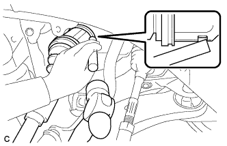
Align the inboard joint splines, and using a brass bar and a hammer, install the front drive shaft assembly LH.
![]() |
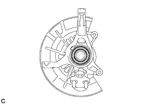
Apply mineral oil base grease to the areas indicated by the arrows in the illustration on the front drive shaft assembly LH contact surface of the front axle hub bearing.
![]() | Mineral Oil Base Grease |
![]() |
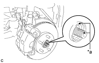
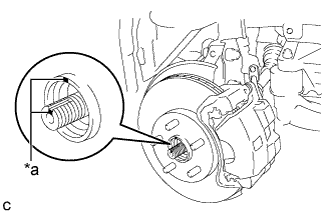
Align the matchmarks and install the front drive shaft assembly LH to the front axle hub sub-assembly.
| *a | Matchmark |
| 2. INSTALL FRONT DRIVE SHAFT ASSEMBLY RH |
Coat the spline of the front drive inboard joint assembly with ATF.
Coat the lip of the front transaxle case oil seal with MP grease.
Install a new bearing bracket hole snap ring to the front drive shaft assembly RH.
Install the front drive shaft assembly RH.
![]() |
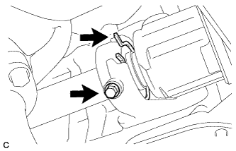
Install the bearing bracket hole snap ring and a new bolt.
![]() |
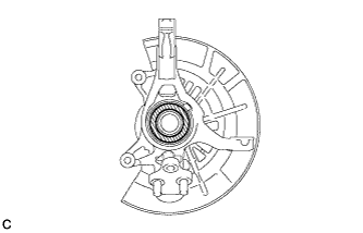
Apply mineral oil base grease to the areas indicated by the arrows in the illustration on the front drive shaft assembly RH contact surface of the front axle hub bearing.
![]() | Mineral Oil Base Grease |
![]() |
Align the matchmarks and install the front drive shaft assembly RH to the front axle hub sub-assembly.
| *a | Matchmark |
| 3. CONNECT FRONT LOWER NO. 1 SUSPENSION ARM SUB-ASSEMBLY |
![]() |
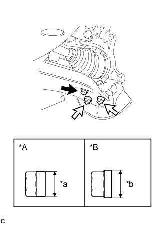
Connect the front lower No. 1 suspension arm sub-assembly to the front lower ball joint assembly with the bolt and 2 nuts.
| *A | Type A Nut |
| *B | Type B Nut |
| *a | 20 mm (0.787 in.) |
| *b | 22 mm (0.866 in.) |
![]() | Bolt |
![]() | Nut |
| 4. CONNECT TIE ROD ASSEMBLY |
Connect the tie rod assembly LH to the steering knuckle with the nut.
Install a new cotter pin.
| 5. INSTALL FRONT SPEED SENSOR |
Install the front speed sensor and front flexible hose to the front shock absorber with the bolt and clamp.
Install the front speed sensor to the steering knuckle with the bolt.
| 6. INSTALL FRONT STABILIZER LINK ASSEMBLY |
Install the front stabilizer link assembly to the front shock absorber assembly with the nut.
| 7. INSTALL FRONT AXLE SHAFT NUT |
Clean the threaded parts on the front drive shaft assembly and a new axle shaft nut using a non-residue solvent.
![]() |
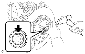
Using a socket wrench (30 mm), install the front axle shaft nut.
Using a chisel and a hammer, stake the front axle shaft nut.
| 8. INSTALL FRONT WHEELS |
| 9. ADD AUTOMATIC TRANSAXLE FLUID |
| 10. INSTALL FRONT FENDER APRON SEAL LH |
| 11. INSTALL FRONT FENDER APRON SEAL RH |
| 12. INSTALL ENGINE UNDER COVER LH |
| 13. INSTALL FRONT WHEEL OPENING EXTENSION PAD LH |
| 14. INSTALL ENGINE UNDER COVER RH |
| 15. INSTALL FRONT WHEEL OPENING EXTENSION PAD RH |
| 16. ADJUST FRONT WHEEL ALIGNMENT |
| 17. CHECK FOR SPEED SENSOR SIGNAL |