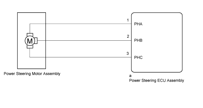
DTC C1524 Motor Circuit Malfunction |
DTC C1555 Motor Relay Welding Failure |
| DTC No. | DTC Detection Condition | Trouble Area |
| C1524 | Short (or open) in motor circuit or abnormal voltage or current in motor circuit |
|
| C1555 | Motor relay circuit malfunction |
| 1.INSPECT TIGHTENING TORQUE OF MOTOR TERMINAL BOLT |
Disengage the 4 claws to remove the protector .
Check that the motor terminal bolts are tightened to the specified torque .
|
| ||||
| OK | |
 |
| 2.INSPECT POWER STEERING MOTOR ASSEMBLY |
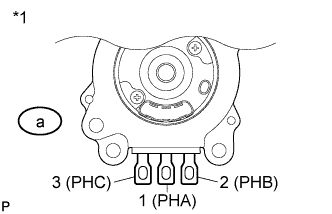 |
Remove the power steering motor assembly (Click here).
Measure the resistance according to the value(s) in the table below.
| Tester Connection | Condition | Specified Condition |
| a-1 (PHA) - a-2 (PHB) | 25°C (77°F) | 12.7 to 17.2 mΩ |
| a-2 (PHB) - a-3 (PHC) | 25°C (77°F) | 12.7 to 17.2 mΩ |
| a-3 (PHC) - a-1 (PHA) | 25°C (77°F) | 12.7 to 17.2 mΩ |
| a-1 (PHA) - Motor case | Always | 10 kΩ or higher |
| a-2 (PHB) - Motor case | Always | 10 kΩ or higher |
| a-3 (PHC) - Motor case | Always | 10 kΩ or higher |
| *1 | Power Steering Motor Assembly |
|
| ||||
| OK | |
|
| 3.READ VALUE USING TECHSTREAM (MOTOR VOLTAGE) |
Turn the engine switch off.
Connect the Techstream to the DLC3.
Start the engine.
Turn the Techstream on.
Enter the following menus: Chassis / EMPS / Data List.
Select the items "Motor Terminal Volt (U)", "Motor Terminal Volt (V)" and "Motor Terminal Volt (W)" in the Data List and read the value displayed on the Techstream.
| Tester Display | Measurement Item/Range | Normal Condition | Diagnostic Note |
| Motor Terminal Volt (U) | Motor terminal voltage (A phase)/ Min.: 0 V Max.: 98.000 V | Value changes within 4 to 35 V range | Engine running and steering wheel being turned |
| Motor Terminal Volt (V) | Motor terminal voltage (B phase)/ Min.: 0 V Max.: 98.000 V | Value changes within 4 to 35 V range | Engine running and steering wheel being turned |
| Motor Terminal Volt (W) | Motor terminal voltage (C phase)/ Min.: 0 V Max.: 98.000 V | Value changes within 4 to 35 V range | Engine running and steering wheel being turned |
| Condition | Proceed to |
| During steering operation, value changes within 4 to 35 V range | A |
| During steering operation, voltage is not generated | B |
|
| ||||
| A | ||
 | ||
| ||
