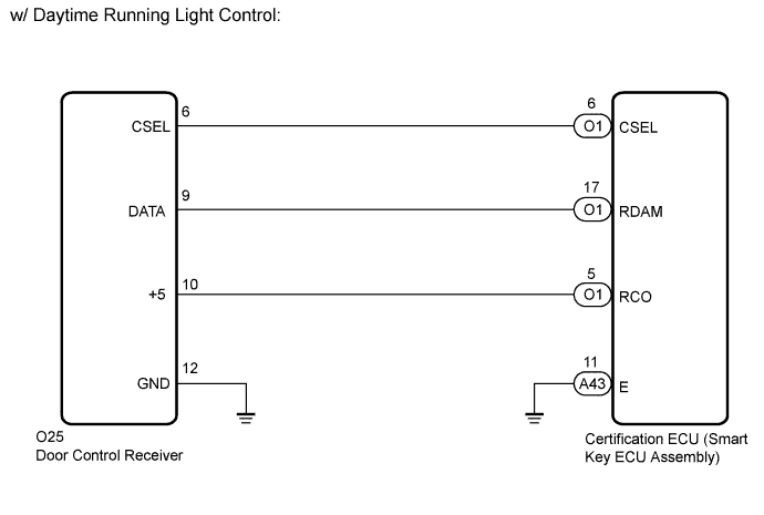
DTC B1242 Wireless Door Lock Tuner Circuit Malfunction |
| DTC No. | DTC Detection Condition | Trouble Area |
| B1242 |
|
|
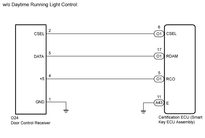
| 1.CHECK CERTIFICATION ECU (SMART KEY ECU ASSEMBLY) |
 |
Disconnect the door control receiver connector.
Measure the resistance and voltage according to the value(s) in the table below.
| Tester Connection | Condition | Specified Condition |
| O25-12 (GND) - Body ground | Always | Below 1 Ω |
| O25-10 (+5) - O25-12 (GND) | Engine switch off, all doors closed and electrical key transmitter sub-assembly switch not pressed → electrical key transmitter sub-assembly switch pressed | Below 1 V → 4.5 to 5.5 V (Pulse generation) |
| O25-9 (DATA) - O25-12 (GND) | Engine switch off | 11 to 14 V pulse generation at regular intervals |
| Tester Connection | Condition | Specified Condition |
| O24-12 (GND) - Body ground | Always | Below 1 Ω |
| O24-4 (+5) - O24-12 (GND) | Engine switch off, all doors closed and electrical key transmitter sub-assembly switch not pressed → electrical key transmitter sub-assembly switch pressed | Below 1 V → 4.5 to 5.5 V (Pulse generation) |
| O24-9 (DATA) - O24-12 (GND) | Engine switch off | 11 to 14 V pulse generation at regular intervals |
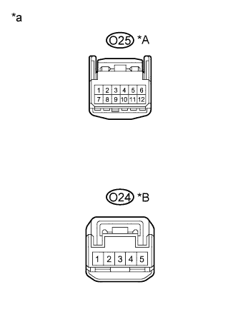
| *A | w/ Daytime Running Light Control |
| *B | w/o Daytime Running Light Control |
| *a | Front view of wire harness connector (Door control receiver) |
| Result | Proceed to |
| NG | A |
| OK (w/ Daytime Running Light Control and w/ Tire Pressure Warning System) | B |
| OK (w/o Daytime Running Light Control or w/o Tire Pressure Warning System) | C |
|
| ||||
|
| ||||
| A | |
 |
| 2.CHECK HARNESS AND CONNECTOR (DOOR CONTROL RECEIVER - CERTIFICATION ECU (SMART KEY ECU ASSEMBLY)) |
Disconnect the certification ECU (smart key ECU assembly) connectors.
Measure the resistance according to the value(s) in the table below.
| Tester Connection | Condition | Specified Condition |
| O1-6 (CSEL) - O25-6 (CSEL) | Always | Below 1 Ω |
| O1-17 (RDAM) - O25-9 (DATA) | Always | Below 1 Ω |
| O1-5 (RCO) - O25-10 (+5) | Always | Below 1 Ω |
| A43-11 (E) - Body ground | Always | Below 1 Ω |
| O25-12 (GND) - Body ground | Always | Below 1 Ω |
| O1-6 (CSEL) or O25-6 (CSEL) - Body ground | Always | 10 kΩ or higher |
| O1-17 (RDAM) or O25-9 (DATA) - Body ground | Always | 10 kΩ or higher |
| O1-5 (RCO) or O25-10 (+5) - Body ground | Always | 10 kΩ or higher |
| Tester Connection | Condition | Specified Condition |
| O1-6 (CSEL) - O24-2 (CSEL) | Always | Below 1 Ω |
| O1-17 (RDAM) - O24-5 (DATA) | Always | Below 1 Ω |
| O1-5 (RCO) - O24-4 (+5) | Always | Below 1 Ω |
| A43-11 (E) - Body ground | Always | Below 1 Ω |
| O24-1 (GND) - Body ground | Always | Below 1 Ω |
| O1-6 (CSEL) or O24-2 (CSEL) - Body ground | Always | 10 kΩ or higher |
| O1-17 (RDAM) or O24-5 (DATA) - Body ground | Always | 10 kΩ or higher |
| O1-5 (RCO) or O24-4 (+5) - Body ground | Always | 10 kΩ or higher |
|
| ||||
| OK | ||
 | ||
| ||
