 |
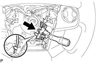
Install the cruise control switch with the 2 screws shown in the illustration.
- Torque:
- 2.4 N*m{ 24 kgf*cm , 21 in.*lbf }
STEERING WHEEL (for 4 Spoke) > INSTALLATION |
| 1. INSTALL STEERING SHAKE DAMPER |
Install the steering shake damper to the steering wheel sub-assembly with the 2 screws.
| 2. INSTALL CRUISE CONTROL SWITCH WIRE |
Install the cruise control switch wire.
| 3. INSTALL CRUISE CONTROL MAIN SWITCH |
Connect the connector.
|
Install the cruise control switch with the 2 screws shown in the illustration.
| 4. INSTALL NO. 1 STEERING WHEEL ORNAMENT (w/o Steering Pad Switch) |
Engage the claw and 2 pins to install the No. 1 steering wheel ornament to the steering wheel sub-assembly.
Install the 2 screws.
| 5. INSTALL NO. 2 STEERING WHEEL ORNAMENT (w/o Steering Pad Switch) |
| 6. INSTALL STEERING PAD SWITCH ASSEMBLY (w/ Steering Pad Switch) |
Engage the claw and 2 pins to install the steering pad switch assembly (RH side) to the steering wheel sub-assembly.
Install the 2 screws.
Engage the claw and 2 pins to install the steering pad switch assembly (LH side) to the steering wheel sub-assembly.
Install the 2 screws.
Connect the steering pad switch connector to the spiral cable sub-assembly.
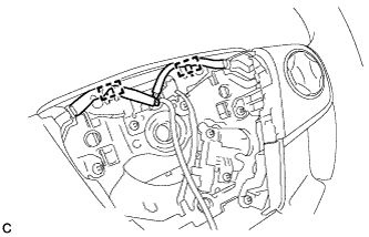 |
Pass the wire harness over the 2 guides.
| 7. ALIGN FRONT WHEELS FACING STRAIGHT AHEAD |
| 8. INSPECT AND ADJUST SPIRAL CABLE WITH SENSOR SUB-ASSEMBLY |
Check that the ignition switch is off.
Check that the cable is disconnected from the negative (-) battery terminal.
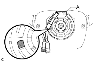 |
Check if the spiral cable sub-assembly is centered.
 | Colored Part |
If the spiral cable sub-assembly is not centered, center it.
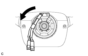 |
While pushing on the interlock indicated in the illustration, rotate the spiral cable sub-assembly counterclockwise slowly by hand until it stops.
 | Interlock |
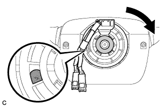 |
Rotate the spiral cable sub-assembly clockwise approximately 2.5 turns to the position where the colored part shown in the illustration is visible.
| Colored Part |
| Interlock |
| 9. INSTALL STEERING WHEEL ASSEMBLY |
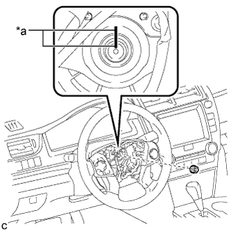 |
Install the steering wheel assembly aligning the matchmarks on the steering wheel assembly and steering main shaft.
| *a | Matchmark |
Install the steering wheel assembly set nut.
Connect the connectors to the spiral cable sub-assembly.
| 10. CHECK STEERING WHEEL CENTER POINT |
| 11. INSTALL HORN BUTTON ASSEMBLY |