 |
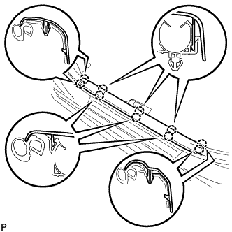
Disengage the 10 claws and remove the front door scuff plate LH.
INSTRUMENT PANEL SAFETY PAD > REMOVAL |
| 1. PRECAUTION |
| 2. DISCONNECT CABLE FROM NEGATIVE BATTERY TERMINAL |
| 3. REMOVE FRONT DOOR SCUFF PLATE LH |
|
Disengage the 10 claws and remove the front door scuff plate LH.
| 4. REMOVE COWL SIDE TRIM SUB-ASSEMBLY LH |
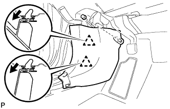 |
Remove the clip.
Disengage the 2 clips and remove the cowl side trim sub-assembly LH.
| 5. DISCONNECT FRONT DOOR OPENING TRIM WEATHERSTRIP LH |
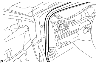 |
Disconnect the front door opening trim weatherstrip LH.
| 6. REMOVE INSTRUMENT SIDE PANEL LH |
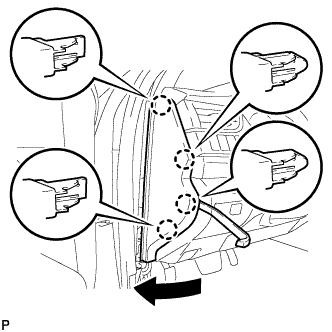 |
Using a moulding remover, disengage the 4 claws as shown in the illustration.
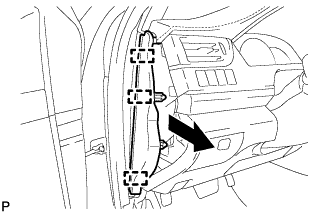 |
Disengage the 3 guides and remove the instrument side panel LH as shown in the illustration.
| 7. REMOVE NO. 1 INSTRUMENT CLUSTER FINISH PANEL GARNISH |
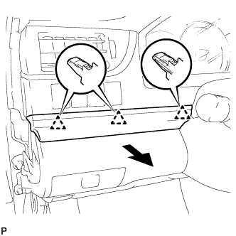 |
Disengage the 3 clips to remove the No. 1 instrument cluster finish panel garnish as shown in the illustration.
| 8. REMOVE NO. 1 INSTRUMENT PANEL REGISTER ASSEMBLY |
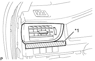 |
Apply protective tape to the area shown in the illustration.
| *1 | Protective Tape |
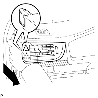 |
Disengage the 2 clips as shown in the illustration.
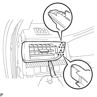 |
Using a moulding remover, disengage the 2 clips to remove the No. 1 instrument panel register assembly.
| 9. REMOVE INSTRUMENT CLUSTER FINISH PANEL ASSEMBLY |
Operate the tilt and telescopic lever to fully extend and lower the steering column assembly.
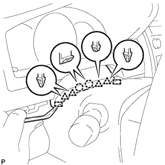 |
Using a moulding remover, disengage the 2 claws, 4 clips and 2 guides.
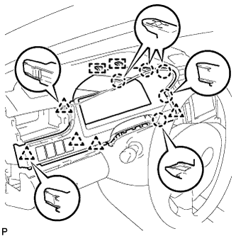 |
Disengage the 5 claws, 5 clips and 2 guides.
Disconnect each connector.
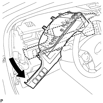 |
Remove the instrument cluster finish panel assembly as shown in the illustration.
| 10. REMOVE COMBINATION METER ASSEMBLY |
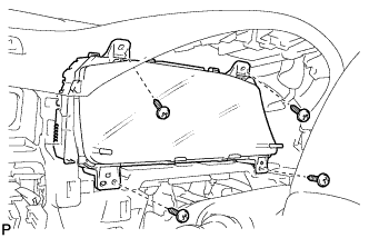 |
Remove the 4 screws.
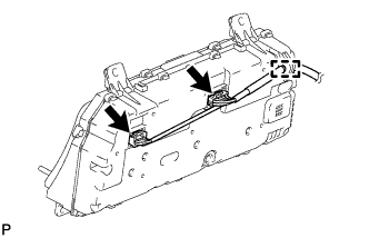 |
Disengage the wire harness clamp.
Disconnect the 2 connectors to remove the combination meter assembly.
| 11. REMOVE FRONT PANEL GARNISH LH |
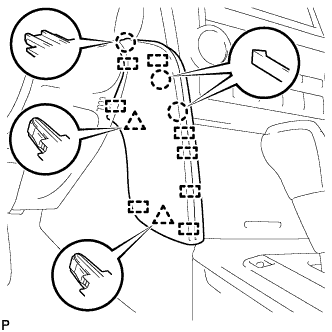 |
Disengage the 3 claws, 2 clips and 8 guides to remove the front panel garnish LH.
| 12. DISCONNECT HOOD LOCK CONTROL LEVER SUB-ASSEMBLY |
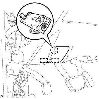 |
Disengage the claw and 2 guides to disconnect the hood lock control lever sub-assembly.
| 13. REMOVE LOWER NO. 1 INSTRUMENT PANEL FINISH PANEL ASSEMBLY |
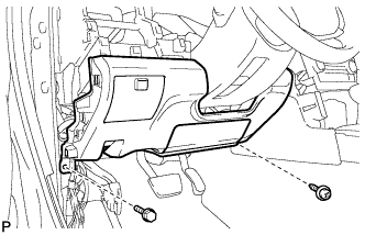 |
Remove the bolt <B> and screw <C> or <D>.
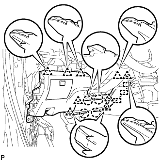 |
Disengage the 4 claws, 9 clips and 3 guides to remove the lower No. 1 instrument panel finish panel assembly.
| 14. REMOVE FRONT PANEL GARNISH RH |
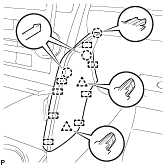 |
Disengage the 3 claws, 2 clips and 8 guides to remove the front panel garnish RH.
| 15. REMOVE SHIFT LEVER KNOB SUB-ASSEMBLY |
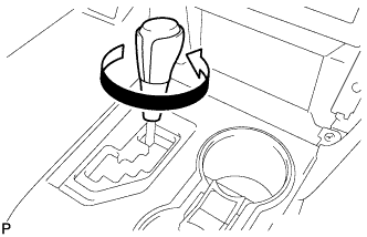 |
Turn the shift lever knob sub-assembly counterclockwise and remove the shift lever knob sub-assembly.
| 16. REMOVE REAR CONSOLE UPPER PANEL SUB-ASSEMBLY |
Move the shift lever to N.
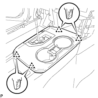 |
Disengage the 4 clips.
w/ Seat heater System:
Disconnect the 2 connectors.
Disconnect the connector and remove the rear console upper panel sub-assembly.
| 17. REMOVE CONSOLE BOX CUP HOLDER |
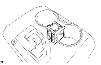 |
Remove the console box cup holder from the rear console upper panel sub-assembly.
| 18. REMOVE INSTRUMENT PANEL CUP HOLDER TRAY |
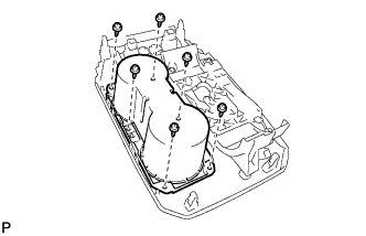 |
Remove the 6 screws <E> and instrument panel cup holder tray.
Remove the front console upper panel garnish.
| 19. REMOVE UPPER CONSOLE BOX SUB-ASSEMBLY |
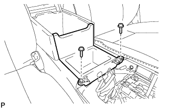 |
Remove the 2 screws.
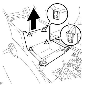 |
Disengage the 4 clips and remove the upper console box sub-assembly as shown in the illustration.
w/ Power Outlet Socket:
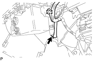 |
Disengage the clamp.
Disconnect the connector to remove the upper console box sub-assembly.
| 20. REMOVE NO. 4 CONSOLE BOX DUCT (w/ Rear Register Duct) |
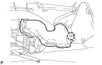 |
Disengage the claw and remove the No. 4 console box duct.
| 21. REMOVE CONSOLE BOX CARPET |
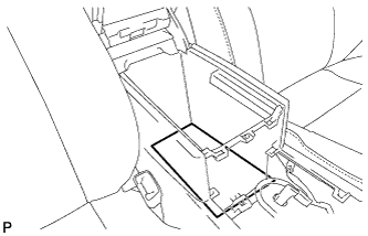 |
Remove the console box carpet.
| 22. REMOVE REAR CONSOLE BOX ASSEMBLY |
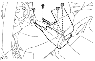 |
Remove the 2 bolts and 2 screws.
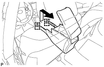 |
Pull the rear console box assembly in the direction indicated by the arrow to disengage the 4 guides and remove the rear console box assembly.
| 23. REMOVE CENTER INSTRUMENT CLUSTER FINISH PANEL ASSEMBLY |
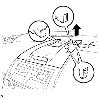 |
Using a moulding remover, disengage the 2 claws and 2 clips as shown in the illustration.
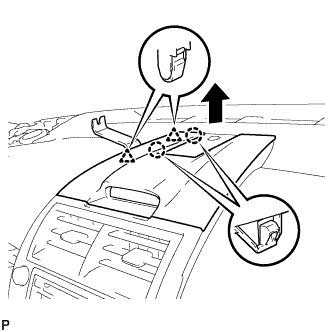 |
Using a moulding remover, disengage the 2 claws and 2 clips as shown in the illustration.
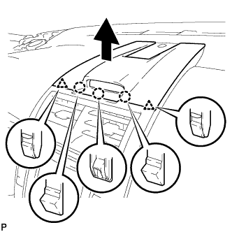 |
Disengage the 3 claws and 2 clips as shown in the illustration.
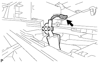 |
Disengage the clamp.
Disconnect the connector to remove the center instrument cluster finish panel assembly.
| 24. REMOVE NO. 2 INSTRUMENT PANEL REGISTER ASSEMBLY |
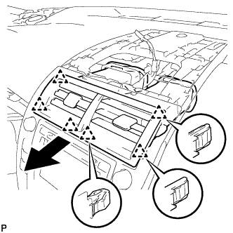 |
Pull the No. 2 instrument panel register assembly in the direction indicated by the arrow to disengage the 6 clips to remove the No. 2 instrument panel register assembly.
| 25. REMOVE BOX BOTTOM MAT |
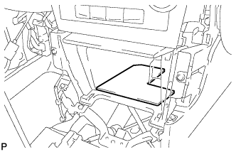 |
Remove the box bottom mat.
| 26. REMOVE UPPER CONSOLE PANEL SUB-ASSEMBLY |
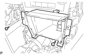 |
Remove the 2 screws <C> or <D>.
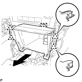 |
Disengage the 4 clips and guide as shown in the illustration.
Disconnect each connector to remove the upper console panel sub-assembly.
| 27. REMOVE RADIO RECEIVER ASSEMBLY WITH AIR CONDITIONING CONTROL ASSEMBLY (for Radio Receiver Type) |
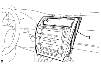 |
Apply protective tape to the area shown in the illustration.
| *1 | Protective Tape |
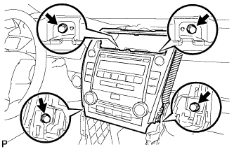 |
Remove the 4 bolts.
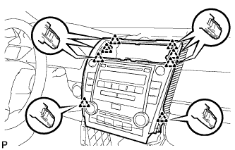 |
Pull the radio receiver assembly with air conditioning control assembly toward the rear of the vehicle and disengage the 8 clips.
Disconnect each connector and remove the radio receiver assembly with air conditioning control assembly.
| 28. REMOVE RADIO RECEIVER ASSEMBLY WITH AIR CONDITIONING CONTROL ASSEMBLY (for Radio and Display Type) |
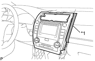 |
Apply protective tape to the area shown in the illustration.
| *1 | Protective Tape |
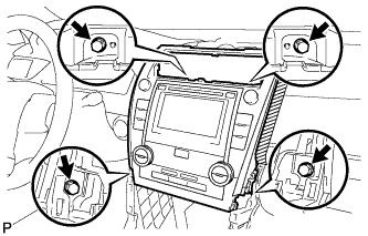 |
Remove the 4 bolts.
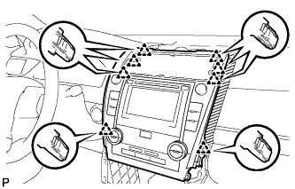 |
Pull the radio receiver assembly with air conditioning control assembly toward the rear of the vehicle and disengage the 8 clips.
Disconnect each connector and remove the radio receiver assembly with air conditioning control assembly.
| 29. REMOVE NAVIGATION RECEIVER ASSEMBLY WITH AIR CONDITIONING CONTROL ASSEMBLY (for Navigation Receiver Type) |
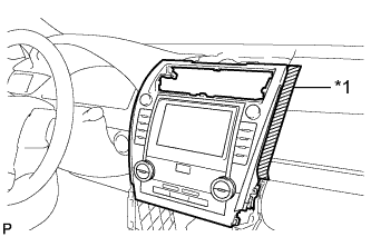 |
Apply protective tape to the area shown in the illustration.
| *1 | Protective Tape |
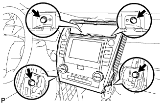 |
Remove the 4 bolts.
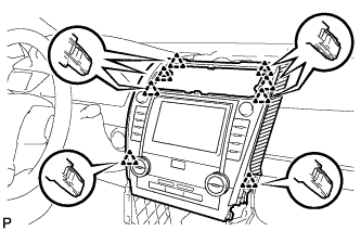 |
Pull the navigation receiver assembly with air conditioning control assembly toward the rear of the vehicle and disengage the 8 clips.
Disconnect each connector and remove the navigation receiver assembly with air conditioning control assembly.
| 30. REMOVE NO. 1 SPEAKER OPENING COVER ASSEMBLY |
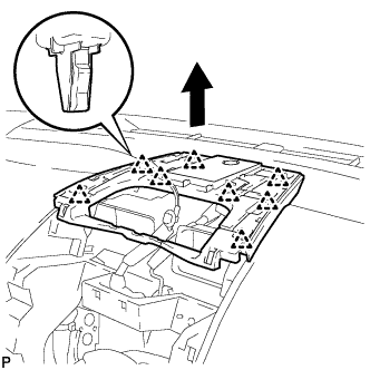 |
Disengage the 8 clips as shown in the illustration.
Disconnect the connector to remove the No. 1 speaker opening cover assembly.
| 31. REMOVE FRONT NO. 3 SPEAKER ASSEMBLY (for 10 Speakers) |
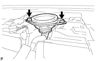 |
Remove the 2 screws.
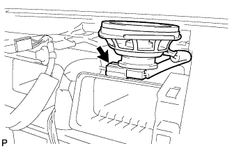 |
Lift the front No. 3 speaker assembly and disconnect the connector to remove the speaker.
| 32. REMOVE FRONT DOOR SCUFF PLATE RH |
| 33. REMOVE COWL SIDE TRIM SUB-ASSEMBLY RH |
| 34. DISCONNECT FRONT DOOR OPENING TRIM WEATHERSTRIP RH |
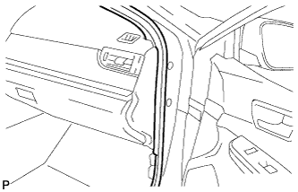 |
Disconnect the front door opening trim weatherstrip RH.
| 35. REMOVE INSTRUMENT SIDE PANEL RH |
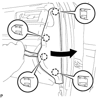 |
Using a moulding remover, disengage the 4 claws as shown in the illustration.
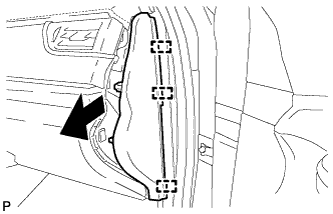 |
Disengage the 3 guides to remove the instrument side panel RH as shown in the illustration.
| 36. REMOVE NO. 2 INSTRUMENT PANEL UNDER COVER SUB-ASSEMBLY |
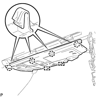 |
Disengage the 4 claws.
Disengage the 2 guides to remove the No. 2 instrument panel under cover sub-assembly.
| 37. REMOVE LOWER NO. 2 INSTRUMENT PANEL AIRBAG ASSEMBLY |
Check that the ignition switch is off.
Check that the cable is disconnected from the negative (-) battery terminal.
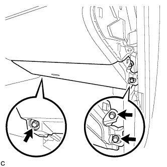 |
Remove the 3 bolts.
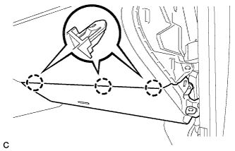 |
Disengage the 3 claws to remove the lower No. 2 instrument panel airbag assembly.
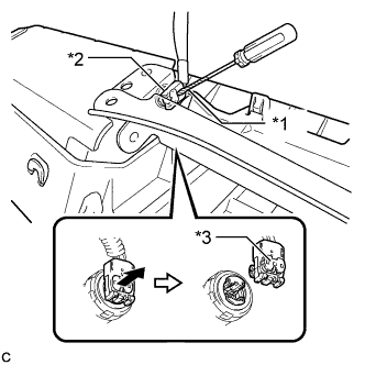 |
Using a screwdriver with the tip wrapped with protective tape, release the airbag connector lock.
| *1 | Protective Tape |
| *2 | Airbag Connector |
| *3 | Airbag Connector Lock |
Disconnect the airbag connector to remove the lower No. 2 instrument panel airbag assembly.
| 38. REMOVE LOWER INSTRUMENT PANEL SUB-ASSEMBLY |
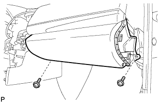 |
Remove the 2 screws <C> or <D>.
Open the lower instrument panel door.
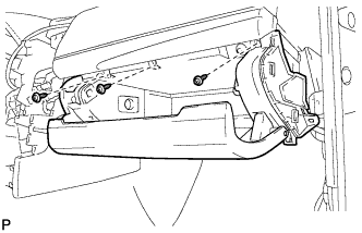 |
Remove the 3 screws <C> or <D>.
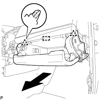 |
Disengage the 2 clips and guide.
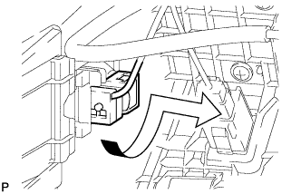 |
Disengage the glove compartment light as shown in the illustration.
Disconnect each connector and remove the lower instrument panel sub-assembly.
| 39. REMOVE NO. 2 INSTRUMENT CLUSTER FINISH PANEL GARNISH |
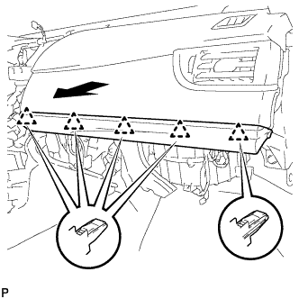 |
Disengage the 5 clips to remove the No. 2 instrument cluster finish panel garnish as shown in the illustration.
| 40. REMOVE NO. 3 INSTRUMENT PANEL REGISTER ASSEMBLY |
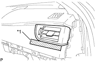 |
Apply protective tape to the area shown in the illustration.
| *1 | Protective Tape |
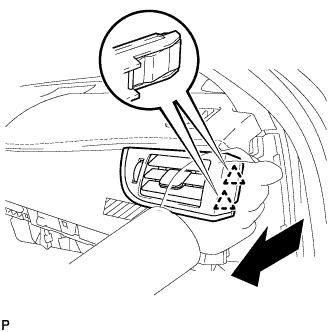 |
Disengage the 2 clips as shown in the illustration.
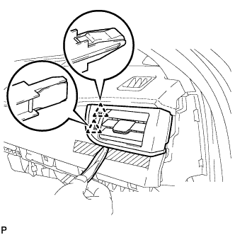 |
Using a moulding remover, disengage the 2 clips to remove the No. 3 instrument panel register assembly.
| 41. REMOVE FRONT PILLAR GARNISH LH |
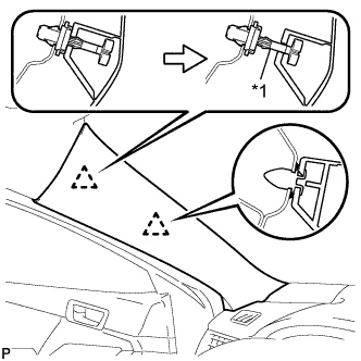 |
Pull the upper part of the garnish toward the inside of the cabin and disengage the garnish from the base of the 2 clips.
| *1 | Front Pillar Garnish Clip |
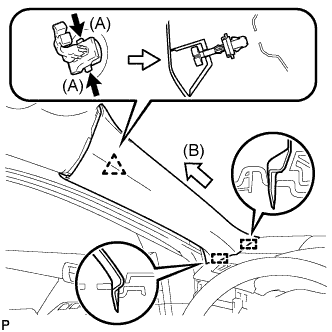 |
While pushing the tabs on the front pillar garnish clip in the direction indicated by the arrow (A) shown in the illustration, disengage the front pillar garnish clip.
Pull the garnish in the direction indicated by the arrow (B) shown in the illustration to disengage the 2 guides and remove the front pillar garnish LH.
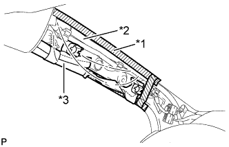 |
Protect the curtain shield airbag assembly.
| *1 | Adhesive Tape |
| *2 | Protective Cover |
| *3 | Curtain Shield Airbag Assembly |
Cover the airbag with a piece of cloth or nylon and secure the edges of the cover with tape as shown in the illustration.
| 42. REMOVE NO. 1 INSTRUMENT PANEL SPEAKER PANEL SUB-ASSEMBLY |
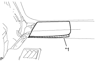 |
Apply protective tape to the area shown in the illustration.
| *1 | Protective Tape |
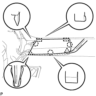 |
Using a moulding remover, disengage the 2 clips and 3 claws.
Disengage the 2 guides to remove the No.1 instrument panel speaker panel sub-assembly.
| 43. REMOVE FRONT NO. 2 SPEAKER ASSEMBLY (for LH Side) |
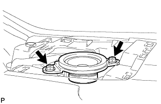 |
Remove the 2 screws.
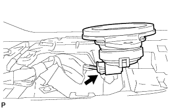 |
Lift the front No. 2 speaker assembly and disconnect the connector to remove the speaker.
| 44. REMOVE FRONT PILLAR GARNISH RH |
| 45. REMOVE NO. 2 INSTRUMENT PANEL SPEAKER PANEL SUB-ASSEMBLY |
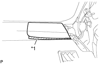 |
Apply protective tape to the area shown in the illustration.
| *1 | Protective Tape |
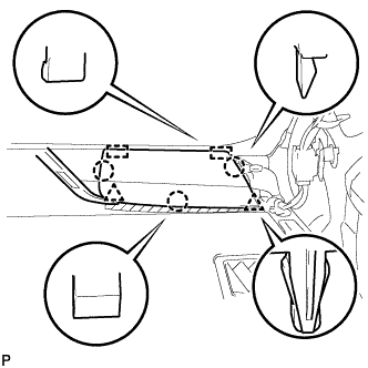 |
Using a moulding remover, disengage the 2 clips and 3 claws.
Disengage the 2 guides to remove the No. 2 instrument panel speaker panel sub-assembly.
| 46. REMOVE FRONT NO. 2 SPEAKER ASSEMBLY (for RH Side) |
| 47. REMOVE LOWER INSTRUMENT PANEL FINISH PANEL ASSEMBLY |
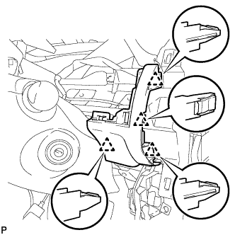 |
Disengage the 4 clips to remove the lower instrument panel finish panel assembly.
w/ Smart Key System:
Disconnect the connector.
| 48. REMOVE FRONT NO. 2 CONSOLE BOX INSERT |
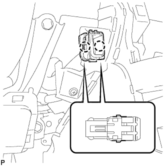 |
Disengage the 2 claws to disconnect the room temperature sensor from the front No. 2 console box insert.
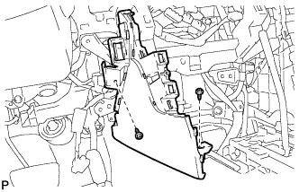 |
Remove the 2 screws <C> or <D>.
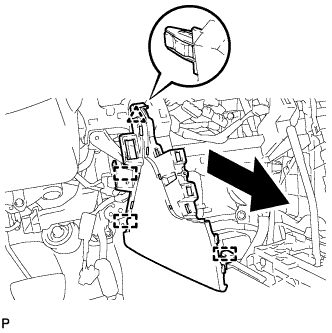 |
Disengage the clip and 3 guides to remove the front No. 2 console box insert as shown in the illustration.
| 49. REMOVE CONSOLE BOX INSERT |
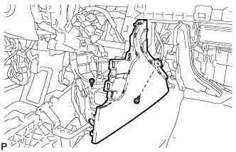 |
Remove the 2 screws <C> or <D>.
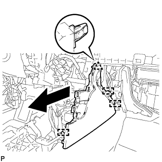 |
Disengage the clip and 3 guides to remove the console box insert as shown in the illustration.
| 50. REMOVE NO. 1 INSTRUMENT PANEL GARNISH SUB-ASSEMBLY |
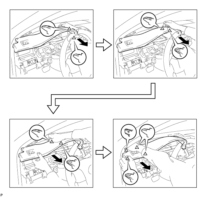
Disengage the 10 clips to remove the No.1 instrument panel garnish sub-assembly as shown in the illustration.
| 51. DISCONNECT NO. 2 INSTRUMENT PANEL WIRE |
Check that the ignition switch is off.
Check that the cable is disconnected from the negative (-) battery terminal.
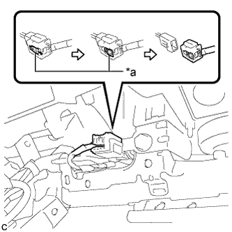 |
Slide the slider to release the lock, and then disconnect the connector.
| *a | Slider |
| 52. REMOVE INSTRUMENT PANEL SAFETY PAD ASSEMBLY |
Disconnect each connector.
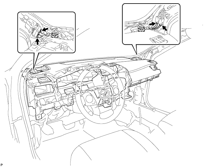
Disengage each clamp.
Remove the 2 passenger airbag bolts <A>.
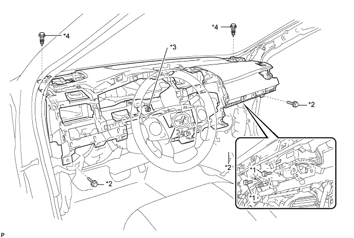
| *1 | Passenger Airbag Bolt <A> | *2 | Bolt <B> |
| *3 | Nut <F> or <G> | *4 | Clip |
Remove the 3 bolts <B> and nut <F> or <G>.
Remove the 2 clips.
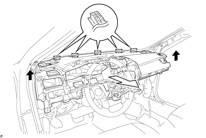
Disengage the 5 guides and remove the instrument panel safety pad assembly as shown in the illustration.