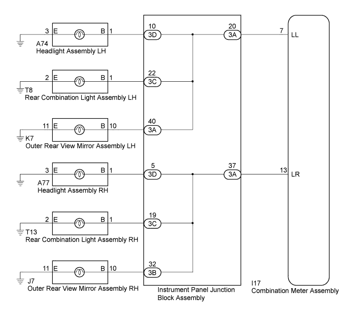
DTC B1507 Open in Turn Signal Circuit |
DTC B1508 Short in Turn Signal / Hazard Flasher Circuit |
| DTC No. | DTC Detection Condition | Trouble Area |
| B1507 | When IG voltage is 9.5 V or more and the following condition is detected:
|
|
| B1508 | When IG voltage is 9.5 V or more and the following condition is detected:
|
|
| 1.INSPECT LIGHTS |
Inspect the illumination of each turn signal light.
| Result | Proceed to |
| Turn signal lights for one side do not illuminate. | A |
| Front turn signal light does not illuminate. | B |
| Rear turn signal light does not illuminate. | C |
| Side turn signal light does not illuminate. | D |
|
| ||||
|
| ||||
|
| ||||
| A | |
 |
| 2.CHECK HARNESS AND CONNECTOR (COMBINATION METER ASSEMBLY - INSTRUMENT PANEL JUNCTION BLOCK ASSEMBLY) |
Disconnect the I17 combination meter assembly connector.
Disconnect the 3A instrument panel junction block assembly connector.
Measure the resistance according to the value(s) in the table below.
| Tester Connection | Condition | Specified Condition |
| I17-7 (LL) - 3A-20 | Always | Below 1 Ω |
| Tester Connection | Condition | Specified Condition |
| I17-13 (LR) - 3A-37 | Always | Below 1 Ω |
| Tester Connection | Condition | Specified Condition |
| I17-7 (LL) - Body ground | Always | 10 kΩ or higher |
| Tester Connection | Condition | Specified Condition |
| I17-13 (LR) - Body ground | Always | 10 kΩ or higher |
| Result | Proceed to |
| NG | A |
| OK | B |
|
| ||||
| A | ||
 | ||
| ||
| 3.CHECK HARNESS AND CONNECTOR (HEADLIGHT ASSEMBLY - INSTRUMENT PANEL JUNCTION BLOCK ASSEMBLY) |
Disconnect the A77*1 or A74*2 headlight assembly connector.
Disconnect the 3D instrument panel junction block assembly connector.
Measure the resistance according to the value(s) in the table below.
| Tester Connection | Condition | Specified Condition |
| A74-1 (B) - 3D-10 | Always | Below 1 Ω |
| A74-3 (E) - Body ground | Always | Below 1 Ω |
| Tester Connection | Condition | Specified Condition |
| A77-1 (B) - 3D-5 | Always | Below 1 Ω |
| A77-3 (E) - Body ground | Always | Below 1 Ω |
| Tester Connection | Condition | Specified Condition |
| A74-1 (B) - Body ground | Always | 10 kΩ or higher |
| Tester Connection | Condition | Specified Condition |
| A77-1 (B) - Body ground | Always | 10 kΩ or higher |
| Result | Proceed to |
| NG | A |
| OK | B |
|
| ||||
| A | ||
| ||
| ||
| 4.CHECK HARNESS AND CONNECTOR (REAR COMBINATION LIGHT ASSEMBLY - INSTRUMENT PANEL JUNCTION BLOCK ASSEMBLY) |
Disconnect the T13*1 or T8*2 rear combination light assembly connector.
Disconnect the 3C and 3D instrument panel junction block assembly connector.
Measure the resistance according to the value(s) in the table below.
| Tester Connection | Condition | Specified Condition |
| T8-1 (B) - 3C-22 | Always | Below 1 Ω |
| T8-2 (E) - Body ground | Always | Below 1 Ω |
| Tester Connection | Condition | Specified Condition |
| T13-1 (B) - 3C-19 | Always | Below 1 Ω |
| T13-2 (E) - Body ground | Always | Below 1 Ω |
| Tester Connection | Condition | Specified Condition |
| T8-1 (B) - Body ground | Always | 10 kΩ or higher |
| Tester Connection | Condition | Specified Condition |
| T13-1 (B) - Body ground | Always | 10 kΩ or higher |
| Result | Proceed to |
| NG | A |
| OK | B |
|
| ||||
| A | ||
| ||
| ||
| 5.CHECK HARNESS AND CONNECTOR (OUTER REAR VIEW MIRROR ASSEMBLY - INSTRUMENT PANEL JUNCTION BLOCK ASSEMBLY) |
Disconnect the J7*1 or K7*2 outer rear view mirror assembly connector.
Disconnect the 3A and 3B instrument panel junction block assembly connector.
Measure the resistance according to the value(s) in the table below.
| Tester Connection | Condition | Specified Condition |
| K7-10 (B) - 3A-40 | Always | Below 1 Ω |
| K7-11 (E) - Body ground | Always | Below 1 Ω |
| Tester Connection | Condition | Specified Condition |
| J7-10 (B) - 3B-32 | Always | Below 1 Ω |
| J7-11 (E) - Body ground | Always | Below 1 Ω |
| Tester Connection | Condition | Specified Condition |
| K7-10 (B) - Body ground | Always | 10 kΩ or higher |
| Tester Connection | Condition | Specified Condition |
| J7-10 (B) - Body ground | Always | 10 kΩ or higher |
| Result | Proceed to |
| NG | A |
| OK | B |
|
| ||||
| A | ||
| ||
| ||
| 6.INSPECT INSTRUMENT PANEL JUNCTION BLOCK ASSEMBLY |
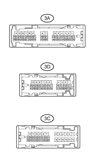 |
Remove the main body ECU (multiplex network body ECU) from the instrument panel junction block assembly (Click here).
Measure the resistance according to the value(s) in the table below.
| Tester Connection | Condition | Specified Condition |
| 3A-37 - 3D-5 | Always | Below 1 Ω |
| 3A-37 - 3C-19 | Always | Below 1 Ω |
| 3A-37 - 3B-32 | Always | Below 1 Ω |
| 3A-20 - 3D-10 | Always | Below 1 Ω |
| 3A-20 - 3C-22 | Always | Below 1 Ω |
| 3A-40 - 3A-20 | Always | Below 1 Ω |
|
| ||||
| OK | ||
| ||
| ||

