Home › Vehicle Exterior › MIRROR (EXT) › POWER MIRROR CONTROL SYSTEM(w/ Memory)
RM2030EQ _59 Vehicle Exterior _014678 MIRROR (EXT) _0074700 POWER MIRROR CONTROL SYSTEM(w/ Memory) J

MIRROR (EXT)  POWER MIRROR CONTROL SYSTEM(w/ Memory)  Power Mirrors do not Return to Memorized Position  


SYSTEM DESCRIPTION

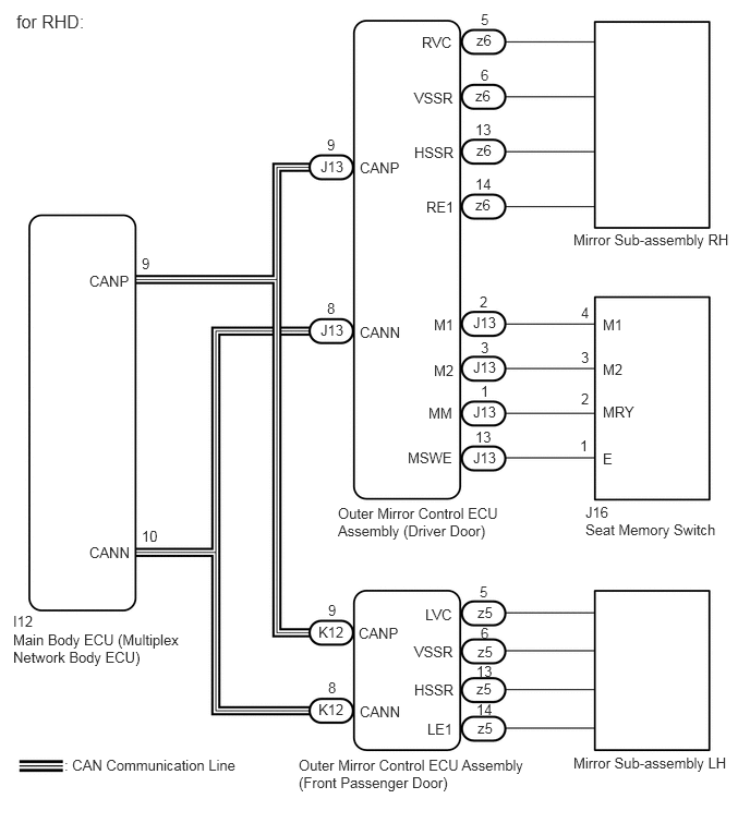
If either the M1 or M2 seat memory switch is pressed, the outer mirror control ECU assembly (driver door) detects the seat memory switch status and sends the switch signal to the main body ECU (multiplex network body ECU) via CAN communication. The main body ECU (multiplex network body ECU) sends back reproduction signals to each outer mirror control ECU assembly via CAN communication. When receiving the reproduction signals, each outer mirror control ECU assembly operates the vertical and horizontal mirror motors, which are built into the mirror sub-assembly, to adjust the mirror surface to the stored position.

WIRING DIAGRAM
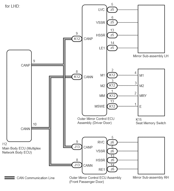
B313725E09
0.094,6.021 1.74,6.719 1.646,0.698 10 false Main Body ECU (Multiplex Network Body ECU) 0.854,5.219 1.531,5.573 0.677,0.354 10 false CANN 0.615,7.24 2.49,7.573 1.875,0.333 10 false : CAN Communication Line 3.427,6.729 3.969,6.969 0.542,0.24 10 false CANN 3.188,4.802 4.771,5.344 1.583,0.542 10 false Outer Mirror Control ECU Assembly (Driver Door) 5.479,2.219 7.073,2.656 1.594,0.438 10 false Mirror Sub-assembly LH 5.469,7.219 7.135,7.521 1.667,0.302 10 false Mirror Sub-assembly RH 2.854,7.229 5.083,7.792 2.229,0.563 10 false Outer Mirror Control ECU Assembly (Front Passenger Door) 3.448,3.083 3.99,3.396 0.542,0.313 10 false CANN 0.865,2.604 1.625,3.219 0.76,0.615 10 false CANP 3.438,5.979 3.979,6.271 0.542,0.292 10 false CANP 3.448,1.51 4.052,1.896 0.604,0.385 10 false CANP 4.5,4.292 4.917,4.594 0.417,0.302 10 false K12 4.51,3.854 4.969,4.115 0.458,0.26 10 false K12 4.5,3.427 4.917,3.688 0.417,0.26 10 false K12 4.5,3 4.875,3.292 0.375,0.292 10 false K12 3.063,6.708 3.438,6.958 0.375,0.25 10 false J13 3.063,5.958 3.448,6.208 0.385,0.25 10 false J13 4.021,5.771 4.552,6.073 0.531,0.302 10 false RVC 4.063,6.896 4.458,7.188 0.396,0.292 10 false RE1 3.958,6.135 4.552,6.448 0.594,0.313 10 false VSSR 3.948,6.51 4.563,6.875 0.615,0.365 10 false HSSR 4.052,0.313 4.615,0.708 0.563,0.396 10 false LVC 4.083,1.896 4.542,2.167 0.458,0.271 10 false LE1 3.958,0.844 4.656,1.198 0.698,0.354 10 false VSSR 3.958,1.365 4.51,1.667 0.552,0.302 10 false HSSR 4.135,3.01 4.5,3.313 0.365,0.302 10 false M1 4.094,3.854 4.542,4.198 0.448,0.344 10 false MM 3.896,4.292 4.49,4.583 0.594,0.292 10 false MSWE 4.135,3.448 4.479,3.708 0.344,0.26 10 false M2 5.74,3.021 6.188,3.365 0.448,0.344 10 false M1 5.74,3.854 6.333,4.177 0.594,0.323 10 false MRY 5.74,4.302 6.042,4.615 0.302,0.313 10 false E 5.74,3.448 6.104,3.74 0.365,0.292 10 false M2 5.542,2.906 5.76,3.167 0.219,0.26 10 false 4 5.542,3.75 5.781,4.031 0.24,0.281 10 false 2 5.542,4.208 5.771,4.417 0.229,0.208 10 false 1 5.552,3.333 5.76,3.542 0.208,0.208 10 false 3 4.583,0.094 4.813,0.375 0.229,0.281 10 false 5 4.552,1.875 4.948,2.198 0.396,0.323 10 false z5 4.552,1.354 4.917,1.688 0.365,0.333 10 false z5 4.552,0.823 4.885,1.188 0.333,0.365 10 false z5 4.552,0.302 4.885,0.531 0.333,0.229 10 false z5 4.552,1.677 4.875,1.969 0.323,0.292 10 false 14 3.135,5.75 3.417,6.125 0.281,0.375 10 false 9 3.125,1.292 3.385,1.552 0.26,0.26 10 false 9 1.354,5.031 1.771,5.375 0.417,0.344 10 false 10 0.094,5.844 0.615,6.219 0.521,0.375 10 false I12 4.552,5.771 4.896,6.052 0.344,0.281 10 false z6 4.552,6.135 4.927,6.417 0.375,0.281 10 false z6 4.563,6.5 4.865,6.792 0.302,0.292 10 false z6 4.563,6.875 4.865,7.135 0.302,0.26 10 false z6 5.594,4.979 7.063,5.438 1.469,0.458 10 false Seat Memory Switch 5.594,4.833 6.135,5.156 0.542,0.323 10 false K15 3.135,6.5 3.354,6.74 0.219,0.24 10 false 8 1.365,2.427 1.844,2.802 0.479,0.375 10 false 9 3.125,2.865 3.365,3.146 0.24,0.281 10 false 8 4.542,4.083 4.854,4.365 0.313,0.281 10 false 13 4.594,0.635 4.875,0.906 0.281,0.271 10 false 6 4.542,1.156 4.854,1.406 0.313,0.25 10 false 13 4.594,2.802 4.729,2.969 0.135,0.167 10 false 2 4.583,3.667 4.833,3.927 0.25,0.26 10 false 1 4.594,3.24 4.865,3.563 0.271,0.323 10 false 3 4.594,5.573 4.771,5.792 0.177,0.219 10 false 5 4.552,6.708 4.823,6.948 0.271,0.24 10 false 14 4.594,5.958 4.792,6.188 0.198,0.229 10 false 6 4.552,6.333 4.844,6.563 0.292,0.229 10 false 13 3.052,1.51 3.438,1.802 0.385,0.292 10 false K12 3.052,3.073 3.469,3.427 0.417,0.354 10 false K12 0.208,0.146 1.167,0.573 0.958,0.427 12 false for LHD:

B313725E10
0.125,6.031 1.771,6.74 1.646,0.708 10 false Main Body ECU (Multiplex Network Body ECU) 0.854,5.198 1.49,5.531 0.635,0.333 10 false CANN 0.615,7.229 2.531,7.594 1.917,0.365 10 false : CAN Communication Line 3.438,6.719 3.927,6.979 0.49,0.26 10 false CANN 3.229,4.823 4.792,5.385 1.563,0.563 10 false Outer Mirror Control ECU Assembly (Driver Door) 5.479,7.208 7.156,7.563 1.677,0.354 10 false Mirror Sub-assembly LH 5.479,2.208 7.021,2.51 1.542,0.302 10 false Mirror Sub-assembly RH 2.854,7.229 5.063,7.677 2.208,0.448 10 false Outer Mirror Control ECU Assembly (Front Passenger Door) 3.438,3.094 4.042,3.458 0.604,0.365 10 false CANN 0.854,2.604 1.469,2.927 0.615,0.323 10 false CANP 3.427,5.969 3.896,6.198 0.469,0.229 10 false CANP 3.438,1.521 4.052,1.854 0.615,0.333 10 false CANP 4.521,4.292 4.948,4.542 0.427,0.25 10 false J13 4.521,3.854 4.885,4.125 0.365,0.271 10 false J13 4.521,3.427 4.865,3.646 0.344,0.219 10 false J13 4.521,3 4.938,3.313 0.417,0.313 10 false J13 3.042,6.698 3.385,6.979 0.344,0.281 10 false K12 3.042,5.958 3.417,6.24 0.375,0.281 10 false K12 4.063,5.792 4.563,6.104 0.5,0.313 10 false LVC 4.083,6.885 4.51,7.146 0.427,0.26 10 false LE1 3.958,6.146 4.51,6.385 0.552,0.24 10 false VSSR 3.958,6.51 4.552,6.813 0.594,0.302 10 false HSSR 4.031,0.323 4.521,0.677 0.49,0.354 10 false RVC 4.073,1.896 4.573,2.167 0.5,0.271 10 false RE1 3.958,0.854 4.521,1.125 0.563,0.271 10 false VSSR 3.958,1.375 4.563,1.656 0.604,0.281 10 false HSSR 4.146,3.021 4.563,3.375 0.417,0.354 10 false M1 4.094,3.865 4.448,4.135 0.354,0.271 10 false MM 3.896,4.292 4.542,4.583 0.646,0.292 10 false MSWE 4.146,3.458 4.51,3.729 0.365,0.271 10 false M2 5.76,3.021 6.24,3.354 0.479,0.333 10 false M1 5.76,3.854 6.219,4.146 0.458,0.292 10 false MRY 5.76,4.302 6.021,4.552 0.26,0.25 10 false E 5.76,3.448 6.125,3.708 0.365,0.26 10 false M2 5.552,2.906 5.74,3.125 0.188,0.219 10 false 4 5.552,3.729 5.813,4.01 0.26,0.281 10 false 2 5.542,4.177 5.771,4.417 0.229,0.24 10 false 1 5.552,3.333 5.771,3.573 0.219,0.24 10 false 3 4.594,0.104 4.854,0.438 0.26,0.333 10 false 5 4.542,1.875 4.969,2.302 0.427,0.427 10 false z6 4.552,0.302 4.906,0.563 0.354,0.26 10 false z6 4.542,0.833 4.802,1.042 0.26,0.208 10 false z6 4.552,1.354 4.896,1.594 0.344,0.24 10 false z6 4.542,1.677 5.01,2.073 0.469,0.396 10 false 14 3.135,5.75 3.344,5.99 0.208,0.24 10 false 9 3.125,1.302 3.375,1.625 0.25,0.323 10 false 9 1.354,5.042 1.729,5.385 0.375,0.344 10 false 10 0.125,5.854 0.646,6.177 0.521,0.323 10 false I12 4.563,5.771 4.813,5.979 0.25,0.208 10 false z5 4.563,6.146 4.875,6.365 0.313,0.219 10 false z5 4.552,6.5 4.917,6.74 0.365,0.24 10 false z5 4.563,6.875 4.896,7.156 0.333,0.281 10 false z5 5.594,4.979 6.938,5.344 1.344,0.365 10 false Seat Memory Switch 5.594,4.813 5.917,5.083 0.323,0.271 10 false J16 3.135,6.49 3.302,6.74 0.167,0.25 10 false 8 1.354,2.438 1.625,2.75 0.271,0.313 10 false 9 3.125,2.865 3.323,3.104 0.198,0.24 10 false 8 4.542,4.094 4.833,4.323 0.292,0.229 10 false 13 4.594,0.635 4.823,0.875 0.229,0.24 10 false 6 4.542,1.156 4.813,1.406 0.271,0.25 10 false 13 4.583,2.802 4.813,3.115 0.229,0.313 10 false 2 4.594,3.656 4.823,3.906 0.229,0.25 10 false 1 4.594,3.24 4.833,3.479 0.24,0.24 10 false 3 4.583,5.573 4.781,5.813 0.198,0.24 10 false 5 4.552,6.698 4.854,6.938 0.302,0.24 10 false 14 4.594,5.969 4.802,6.198 0.208,0.229 10 false 6 4.552,6.333 4.854,6.563 0.302,0.229 10 false 13 3.063,3.073 3.396,3.323 0.333,0.25 10 false J13 3.063,1.51 3.531,1.813 0.469,0.302 10 false J13 0.156,0.104 1.24,0.698 1.083,0.594 12 false for RHD:

PROCEDURE

1.CHECK CAN COMMUNICATION SYSTEM
a.

Use the intelligent tester to check if the CAN communication system is functioning normally.

Click herePower Source / Network>NETWORKING>CAN COMMUNICATION SYSTEM>DIAGNOSIS SYSTEM

OK:

CAN communication DTC is not output.


Result:
Proceed to
OK
NG


OK

2.CHECK SEAT MEMORY SWITCH FUNCTION

NG

GO TO CAN COMMUNICATION SYSTEM (DIAGNOSTIC TROUBLE CODE CHART)

2.CHECK SEAT MEMORY SWITCH FUNCTION
a.

When any seat memory switch (M1 or M2 switch) is pressed, check that the driver seat moves to the memorized position.

OK:

The driver seat moves to the memorized position.


Result:
Proceed to
OK
NG


OK

3.CHECK POWER MIRROR CONTROL FUNCTION (ELECTRICAL REMOTE CONTROL MIRROR FUNCTION)

NG

GO TO POWER SEAT CONTROL SYSTEM (Power Seat does not Return to Memorized Position)

3.CHECK POWER MIRROR CONTROL FUNCTION (ELECTRICAL REMOTE CONTROL MIRROR FUNCTION)
a.

Check the electrical remote control mirror function.

Click hereVehicle Exterior>MIRROR (EXT)>POWER MIRROR CONTROL SYSTEM(w/ Memory)>OPERATION CHECK

OK:

Electrical remote control mirror function is normal.


Result:
Proceed to
OK
NG


OK

4.READ VALUE USING INTELLIGENT TESTER (MIRROR POSITION MEMORY)

NG

4.READ VALUE USING INTELLIGENT TESTER (MIRROR POSITION MEMORY)
a.

Connect the intelligent tester to the DLC3.


b.

Turn the engine switch on (IG).


c.

Turn the intelligent tester on.


d.

Enter the following menus: Body / Mirror L or Mirror R / Data List.


e.

Read the Data List according to the display on the intelligent tester.

Body Electrical > Mirror L > Data List
Tester Display Measurement Item Range Normal Condition Diagnostic Note
Mirror Memory No.1 Mirror position memorized in seat memory switch M1 ON or OFF ON: Memorized
OFF: Not memorized
-
Mirror Memory No.2 Mirror position memorized in seat memory switch M2 ON or OFF ON: Memorized
OFF: Not memorized
-
Body Electrical > Mirror L > Data List
Tester Display
Mirror Memory No.1
Mirror Memory No.2
50003 225 5,6
Body Electrical > Mirror R > Data List
Tester Display Measurement Item Range Normal Condition Diagnostic Note
Mirror Memory No.1 Mirror position memorized in seat memory switch M1 ON or OFF ON: Memorized
OFF: Not memorized
-
Mirror Memory No.2 Mirror position memorized in seat memory switch M2 ON or OFF ON: Memorized
OFF: Not memorized
-
Body Electrical > Mirror R > Data List
Tester Display
Mirror Memory No.1
Mirror Memory No.2
50003 224 5,6
OK:

ON (Memorized) appears on the screen.


Result:
Proceed to
OK
NG


OK

5.CHECK MEMORY AND REACTIVATION FUNCTION

NG

GO TO OTHER DIAGNOSIS PROCEDURE (Power Mirror Surface Position is not Memorized)

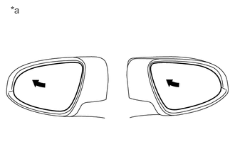
5.CHECK MEMORY AND REACTIVATION FUNCTION
a.
B293945C06
0.155,0.062 0.311,0.232 0.156,0.17 10 *a
*a Turn to Left Fully


Turn the engine switch on (IG).


b.

Using the outer mirror switch assembly, turn the mirror surface to the fully left position.


c.

Press the M1 switch while the SET switch is being pressed.


d.

Check that the buzzer sounds for 0.5 seconds and the mirror surface position is memorized.


e.

Using the outer mirror switch assembly, turn the mirror surface to the fully right position.


f.

Press the M1 switch.


g.

Check that the buzzer sounds for 0.1 seconds and the outer mirror automatically moves to the recorded fully left position.

Result:
Result Proceed to
Memory and reactivation functions on both mirrors are not normal A
Memory and reactivation functions on RH side mirror are not normal B
Memory and reactivation functions on LH side mirror are not normal C


A

REPLACE MAIN BODY ECU (MULTIPLEX NETWORK BODY ECU)

B

6.REPLACE MIRROR SUB-ASSEMBLY RH

C

8.REPLACE MIRROR SUB-ASSEMBLY LH
6.REPLACE MIRROR SUB-ASSEMBLY RH
a.

Replace the mirror sub-assembly RH.

Click hereVehicle Exterior>MIRROR (EXT)>OUTER REAR VIEW MIRROR>REMOVAL


Result:
Proceed to
NEXT


NEXT

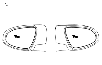
7.CHECK MEMORY AND REACTIVATION FUNCTION
a.
B293945C07
0.155,0.062 0.311,0.232 0.156,0.17 10 *a
*a Turn to Left Fully


Turn the engine switch on (IG).


b.

Using the outer mirror switch assembly, turn the mirror surface to the fully left position.


c.

Press the M1 switch while the SET switch is being pressed.


d.

Check that the buzzer sounds for 0.5 seconds and the mirror surface position is memorized.


e.

Using the outer mirror switch assembly, turn the mirror surface to the fully right position.


f.

Press the M1 switch.


g.

Check that the buzzer sounds for 0.1 seconds and the outer mirror automatically moves to the recorded fully left position.

OK:

Memory and reactivation function is normal.


Result:
Proceed to
OK
NG


OK

END (MIRROR SUB-ASSEMBLY RH WAS DEFECTIVE)

NG

REPLACE OUTER MIRROR CONTROL ECU ASSEMBLY (DRIVER DOOR)

8.REPLACE MIRROR SUB-ASSEMBLY LH
a.

Replace the mirror sub-assembly LH.

Click hereVehicle Exterior>MIRROR (EXT)>OUTER REAR VIEW MIRROR>REMOVAL


Result:
Proceed to
NEXT


NEXT

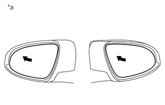
9.CHECK MEMORY AND REACTIVATION FUNCTION
a.
B293945C08
0.155,0.062 0.311,0.232 0.156,0.17 10 *a
*a Turn to Left Fully


Turn the engine switch on (IG).


b.

Using the outer mirror switch assembly, turn the mirror surface to the fully left position.


c.

Press the M1 switch while the SET switch is being pressed.


d.

Check that the buzzer sounds for 0.5 seconds and the mirror surface position is memorized.


e.

Using the outer mirror switch assembly, turn the mirror surface to the fully right position.


f.

Press the M1 switch.


g.

Check that the buzzer sounds for 0.1 seconds and the outer mirror automatically moves to the recorded fully left position.

OK:

Memory and reactivation function is normal.


Result:
Proceed to
OK
NG


OK

END (MIRROR SUB-ASSEMBLY LH WAS DEFECTIVE)

NG

REPLACE OUTER MIRROR CONTROL ECU ASSEMBLY (FRONT PASSENGER DOOR)