RM2030EQ
_56
Audio / Visual / Telematics
_014658
AUDIO / VIDEO
_0076716
AUDIO AND VISUAL SYSTEM(for Radio and Display Type)
J
AUDIO / VIDEO AUDIO AND VISUAL SYSTEM(for Radio and Display Type) Reverse Signal Circuit
DESCRIPTION
The radio and display receiver assembly receives a reverse signal from the park/neutral position switch assembly.
WIRING DIAGRAM
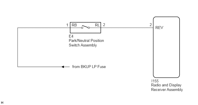
2.396,0.823 2.667,1.052
0.271,0.229
10
1
3.729,0.813 4,1
0.271,0.188
10
2
5.417,0.813 5.719,1.052
0.302,0.24
10
2
2.594,0.823 3.031,1.167
0.438,0.344
10
RB
3.438,0.823 3.885,1.104
0.448,0.281
10
RL
2.49,1.229 2.802,1.417
0.313,0.188
10
E4
2.49,1.385 3.833,1.74
1.344,0.354
10
Park/Neutral Position Switch Assembly
5.625,0.917 6.073,1.188
0.448,0.271
10
REV
5.479,2.854 6.042,3.104
0.563,0.25
10
I155
5.469,3 6.708,3.479
1.24,0.479
10
Radio and Display Receiver Assembly
2.615,2.333 4.115,2.667
1.5,0.333
10
from BKUP LP Fuse
PROCEDURE
1.CHECK HARNESS AND CONNECTOR (REVERSE SIGNAL)
a.
Disconnect the radio and display receiver assembly connector.
b.
Measure the voltage according to the value(s) in the table below.
- Standard Voltage:
Tester Connection Condition Specified Condition I155-2 (REV) - Body ground Ignition switch ON
Shift lever in R11 to 14 V I155-2 (REV) - Body ground Ignition switch ON
Shift lever in any position other than RBelow 1 V
- Result:
Proceed to OK NG
OK
PROCEED TO NEXT SUSPECTED AREA SHOWN IN PROBLEM SYMPTOMS TABLE
NG
2.CHECK HARNESS AND CONNECTOR (RADIO AND DISPLAY RECEIVER ASSEMBLY - PARK/NEUTRAL POSITION SWITCH ASSEMBLY)
2.CHECK HARNESS AND CONNECTOR (RADIO AND DISPLAY RECEIVER ASSEMBLY - PARK/NEUTRAL POSITION SWITCH ASSEMBLY)
a.
Disconnect the radio and display receiver assembly connector.
b.
Disconnect the park/neutral position switch assembly connector.
c.
Measure the resistance according to the value(s) in the table below.
- Standard Resistance:
Tester Connection Condition Specified Condition I155-2 (REV) - E4-2 (RL) Always Below 1 Ω I155-2 (REV) - Body ground Always 10 kΩ or higher
- Result:
Proceed to OK NG
OK
3.CHECK HARNESS AND CONNECTOR (PARK/NEUTRAL POSITION SWITCH ASSEMBLY - BATTERY)
NG
REPAIR OR REPLACE HARNESS OR CONNECTOR
3.CHECK HARNESS AND CONNECTOR (PARK/NEUTRAL POSITION SWITCH ASSEMBLY - BATTERY)
a.
Disconnect the park/neutral position switch assembly connector.
b.
Measure the voltage according to the value(s) in the table below.
- Standard Voltage:
Tester Connection Condition Specified Condition E4-1 (RB) - Body ground Ignition switch ON 11 to 14 V
- Result:
Proceed to OK NG
OK
REPLACE PARK/NEUTRAL POSITION SWITCH ASSEMBLY
Click hereDrivetrain>U660E AUTOMATIC TRANSMISSION / TRANSAXLE>PARK / NEUTRAL POSITION SWITCH>REMOVAL
NG
REPAIR OR REPLACE HARNESS OR CONNECTOR