METER / GAUGE / DISPLAY METER / GAUGE SYSTEM Meter Illumination is Always Dark
DESCRIPTION
The meter ECU receives signals from this circuit to adjust the illumination of the meter. The meter ECU sets the illumination level based on the user operation of the light control rheostat switch.
- HINT:
- ·
The meter illumination level can be adjusted by operating the light control rheostat switch.
·The meter illumination dims when the light control switch is turned to the tail, head, or AUTO position.
·Setting the meter illumination to maximum brightness cancels the above dimming of the meter illumination.
WIRING DIAGRAM
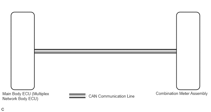
CAUTION / NOTICE / HINT
- HINT:
- ·
The meter illumination can be customized by turning the light control rheostat switch.
·Setting the meter illumination to minimum brightness turns off the meter illumination when the light control switch is changed to the tail, head, or AUTO position.
·Before starting the following inspection, check if lighting system DTCs are output.
Click hereVehicle Exterior>LIGHTING (EXT)>LIGHTING SYSTEM>DTC CHECK / CLEAR
PROCEDURE
Check if CAN communication DTCs are output.
Click herePower Source / Network>NETWORKING>CAN COMMUNICATION SYSTEM>DIAGNOSIS SYSTEM
- Result:
Result Proceed to DTCs are not output. A DTCs are output. B
A
B
Click herePower Source / Network>NETWORKING>CAN COMMUNICATION SYSTEM>HOW TO PROCEED WITH TROUBLESHOOTING
Connect the intelligent tester to the DLC3.
Turn the ignition switch to ON.
Turn the intelligent tester on.
Enter the following menus: Body / Main Body / Data List.
Check the values by referring to the table below.
- Body Electrical > Main Body > Data List
-
Tester Display Measurement Item Range Normal Condition Diagnostic Note Illumination Rate Info Illumination rate information 0 ms. to 2162.65 ms. Value output according to ambient light level -
- Body Electrical > Main Body > Data List
-
Tester Display Illumination Rate Info - 50003 123 61
- Result:
Result Proceed to The output value changes according to the ambient light level. A The output value does not change according to the ambient light level. B
- HINT:
-
If the output value does not change according to the ambient light level, check the automatic light control sensor sensitivity setting.
A
B
Replace the main body ECU (multiplex network body ECU) with a new or a known good one.
Click herePower Source / Network>POWER DISTRIBUTION>MAIN BODY ECU>REMOVAL
- OK:
The operation of the combination meter assembly returns to normal.
- HINT:
-
The meter ECU controls the meter illumination based on an auto dimmer signal from the main body ECU (multiplex network body ECU). When the meter illumination is always dark (very dim), it may be due to the main body ECU (multiplex network body ECU) sending an auto dimmer signal to the meter ECU because of a malfunction in the main body ECU (multiplex network body ECU).
- Result:
Proceed to OK NG
OK
NG