Home › Steering › POWER ASSIST SYSTEMS › POWER STEERING SYSTEM › 2012.02–2015.04
RM2040EQ _55 Steering _014713 POWER ASSIST SYSTEMS _0074999 POWER STEERING SYSTEM J

POWER ASSIST SYSTEMS  POWER STEERING SYSTEM  TC and CG Terminal Circuit  


DESCRIPTION

Connecting terminals TC and CG of the DLC3 causes the ECU to display DTCs by blinking the EPS warning light.

WIRING DIAGRAM
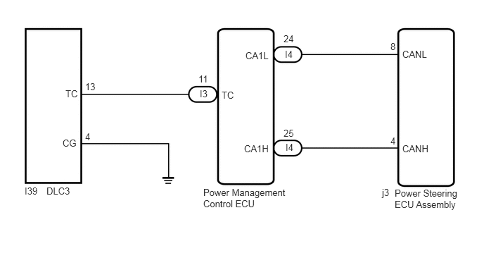
C246730E08
1.26,1.198 1.438,1.354 0.177,0.156 10 false 13 0.969,1.302 1.146,1.49 0.177,0.188 10 false TC 2.958,1.302 3.104,1.458 0.146,0.156 10 false I3 2.938,1.083 3.115,1.24 0.177,0.156 10 false 11 4.219,0.719 4.375,0.885 0.156,0.167 10 false I4 4.198,0.49 4.427,0.719 0.229,0.229 10 false 24 3.635,0.74 4.052,0.948 0.417,0.208 10 false CA1L 4.229,2.094 4.375,2.26 0.146,0.167 10 false I4 4.198,1.885 4.385,2.052 0.188,0.167 10 false 25 3.615,2.115 4.031,2.313 0.417,0.198 10 false CA1H 5.958,0.719 6.354,0.917 0.396,0.198 10 false CANL 5.781,0.604 5.875,0.76 0.094,0.156 10 false 8 5.781,2 5.875,2.156 0.094,0.156 10 false 4 5.958,2.115 6.375,2.313 0.417,0.198 10 false CANH 1.26,1.938 1.438,2.094 0.177,0.156 10 false 4 0.927,2.031 1.146,2.219 0.219,0.188 10 false CG 0.365,2.74 0.563,2.938 0.198,0.198 10 false I39 0.688,2.74 1.073,2.979 0.385,0.24 10 false DLC3 3.01,2.76 4.313,3.24 1.302,0.479 10 false Power Management Control ECU 5.844,2.771 6.854,3.271 1.01,0.5 10 false Power Steering ECU Assembly 5.656,2.76 5.833,2.938 0.177,0.177 10 false j3 3.281,1.323 3.49,1.479 0.208,0.156 10 false TC

CAUTION / NOTICE / HINT

NOTICE:

If the power steering ECU assembly has been replaced, perform assist map writing.

Click hereSteering>POWER ASSIST SYSTEMS>POWER STEERING SYSTEM>CALIBRATION


HINT:

When the warning lights continue to blink, a ground short in the wiring of terminal TC of the DLC3 or an internal ground short in one or more ECUs is suspected.


PROCEDURE

1.CHECK CAN COMMUNICATION SYSTEM
a.

Check if a CAN communication system DTC is output.

Click herePower Source / Network>NETWORKING>CAN COMMUNICATION SYSTEM>DIAGNOSIS SYSTEM


Result:
Result Proceed to
DTCs are not output. A
DTCs are output. B


A

2.CHECK HARNESS AND CONNECTOR (TC of DLC3 - POWER MANAGEMENT CONTROL ECU)

B

2.CHECK HARNESS AND CONNECTOR (TC of DLC3 - POWER MANAGEMENT CONTROL ECU)
a.

Disconnect the power management control connector.


b.

Measure the resistance according to the value(s) in the table below.

Standard Resistance:
for 2AR-FE
Tester Connection Condition Specified Condition
I39-13 (TC) - I3-11 (TC) Always Below 1 Ω


Result:
Proceed to
OK
NG


OK

3.CHECK HARNESS AND CONNECTOR (CG of DLC3 - BODY GROUND)

NG

REPAIR OR REPLACE HARNESS OR CONNECTOR

3.CHECK HARNESS AND CONNECTOR (CG of DLC3 - BODY GROUND)
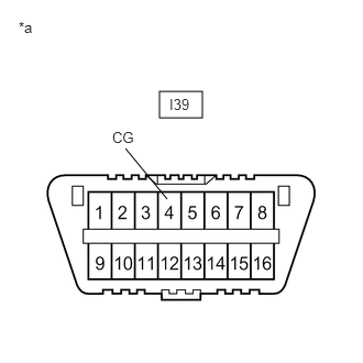
a.
C207407C47
1.51,0.865 1.917,1.115 0.406,0.25 1.188,1.406 1.583,1.885 false 0.177,0.177 0.75,0.594 0.573,0.417 10 *a 1.063,1.219 1.406,1.458 0.344,0.24 10 CG 1.604,0.906 2.01,1.281 0.406,0.375 10 I39
*a Front view of DLC3


Measure the resistance according to the value(s) in the table below.

Standard Resistance:
Tester Connection Condition Specified Condition
I39-4 (CG) - Body ground Always Below 1 Ω


Result:
Proceed to
OK
NG


OK

4.CHECK HARNESS AND CONNECTOR (TC of DLC3 - BODY GROUND)

NG

REPAIR OR REPLACE HARNESS OR CONNECTOR

4.CHECK HARNESS AND CONNECTOR (TC of DLC3 - BODY GROUND)
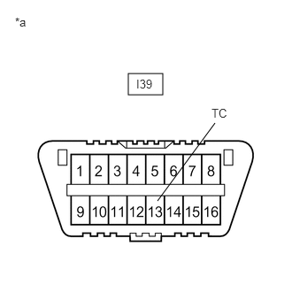
a.
C207407C51
1.51,0.865 1.917,1.115 0.406,0.25 2.531,1.448 1.854,2.365 false 0.177,0.177 0.75,0.594 0.573,0.417 10 *a 2.49,1.25 2.833,1.49 0.344,0.24 10 TC 1.604,0.906 2.01,1.281 0.406,0.375 10 I39
*a Front view of DLC3


Measure the resistance according to the value(s) in the table below.

Standard Resistance:
Tester Connection Condition Specified Condition
I39-13 (TC) - Body ground Always 10 kΩ or higher


Result:
Proceed to
OK
NG


OK

REPLACE POWER STEERING ECU ASSEMBLY

NG

REPAIR OR REPLACE WIRE HARNESS OR EACH ECU