0.175,3.551 2.171,4.044
1.996,0.493
10
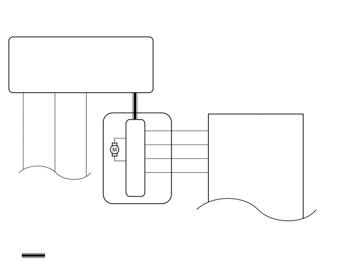
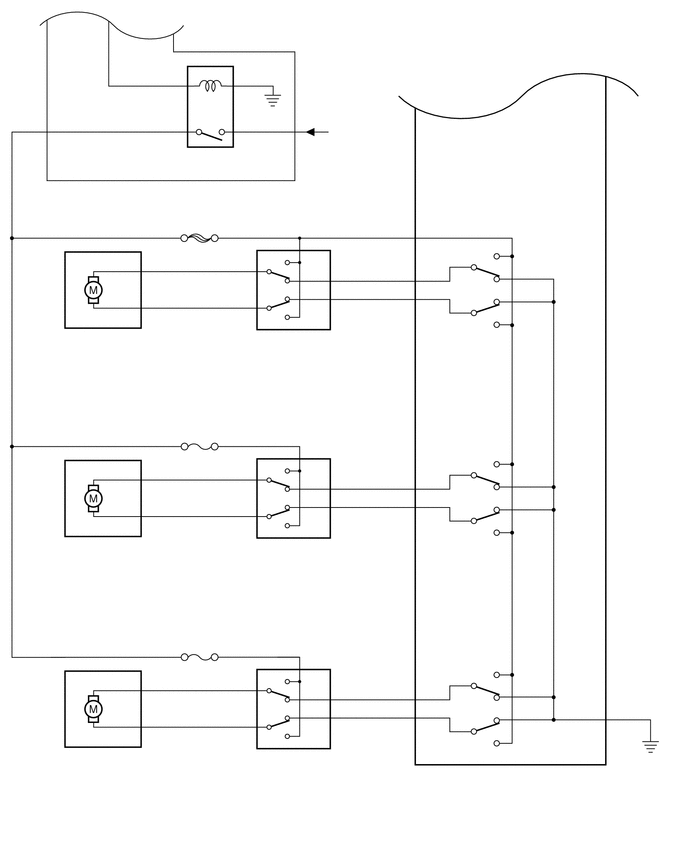
Power Window Regulator Motor Assembly (for Front Passenger Door)
0.483,1.87 3.200,2.067
2.717,0.198
10
Instrument Panel Junction Block Assembly
2.258,3.551 4.303,4.044
2.045,0.493
10
Power Window Regulator Switch Assembly (for Front Passenger Door)
0.184,5.601 2.180,6.146
1.996,0.545
10
Power Window Regulator Motor Assembly (for Rear LH Door)
2.29,5.601 4.335,5.948
2.045,0.347
10
Power Window Regulator Switch Assembly (for Rear LH Door)
0.1,7.796 2.096,8.154
1.996,0.358
10
Power Window Regulator Motor Assembly (for Rear RH Door)
2.225,7.796 4.270,8.143
2.045,0.347
10
Power Window Regulator Switch Assembly (for Rear RH Door)
4.517,8.124 6.107,8.471
1.590,0.347
10
Power Window Regulator Master Switch Assembly
1.973,1.533 2.425,1.688
0.452,0.155
10
DOOR
3.463,1.253 4.343,1.630
0.880,0.377
10
from Auxiliary Battery
1.717,2.515 2.569,2.670
0.852,0.155
10
DOOR NO. 1
1.731,4.673 2.472,4.828
0.740,0.155
10
DOOR R/L
1.731,6.873 2.476,7.027
0.745,0.155
10
DOOR R/R
4.384,7.101 4.512,7.243
0.128,0.142
10
U
2.717,6.982 2.845,7.124
0.128,0.142
10
U
3.172,6.954 3.300,7.096
0.128,0.142
10
B
3.172,4.748 3.300,4.890
0.128,0.142
10
B
3.172,2.59 3.300,2.732
0.128,0.142
10
B
2.717,4.776 2.845,4.918
0.128,0.142
10
U
2.717,2.618 2.845,2.760
0.128,0.142
10
U
2.583,2.618 2.684,2.760
0.100,0.142
10
4
2.583,4.818 2.684,4.960
0.100,0.142
10
4
3.487,4.909 3.587,5.051
0.100,0.142
10
5
3.487,2.73 3.587,2.872
0.100,0.142
10
5
4.141,2.73 4.353,2.872
0.211,0.142
10
12
4.208,2.275 4.317,2.417
0.109,0.142
10
6
4.131,4.909 4.316,5.051
0.185,0.142
10
18
4.131,7.101 4.316,7.243
0.185,0.142
10
16
6.372,7.305 6.645,7.447
0.272,0.142
10
9
4.135,7.466 4.316,7.608
0.182,0.142
10
15
4.131,5.259 4.305,5.401
0.174,0.142
10
10
4.141,3.11 4.331,3.252
0.190,0.142
10
13
3.487,7.101 3.587,7.243
0.100,0.142
10
5
3.487,5.259 3.587,5.401
0.100,0.142
10
2
3.487,3.094 3.587,3.236
0.100,0.142
10
2
3.487,7.466 3.587,7.608
0.100,0.142
10
2
1.526,4.804 1.626,4.946
0.100,0.142
10
1
1.526,3.01 1.626,3.152
0.100,0.142
10
1
2.583,6.996 2.684,7.138
0.100,0.142
10
4
1.519,6.996 1.619,7.138
0.100,0.142
10
1
2.583,3.024 2.684,3.166
0.100,0.142
10
1
2.583,5.203 2.684,5.345
0.100,0.142
10
1
1.526,5.189 1.626,5.331
0.100,0.142
10
2
1.526,2.639 1.626,2.781
0.100,0.142
10
2
2.583,7.375 2.684,7.517
0.100,0.142
10
1
1.519,7.375 1.619,7.517
0.100,0.142
10
2
1.337,6.996 1.465,7.138
0.128,0.142
10
U
1.337,4.811 1.465,4.953
0.128,0.142
10
U
1.337,2.632 1.465,2.774
0.128,0.142
10
U
4.384,4.909 4.512,5.051
0.128,0.142
10
U
4.384,2.73 4.512,2.872
0.128,0.142
10
U
3.235,2.73 3.453,2.872
0.218,0.142
10
SU
3.235,4.909 3.453,5.051
0.218,0.142
10
SU
3.235,7.101 3.453,7.243
0.218,0.142
10
SU
3.235,3.101 3.453,3.243
0.218,0.142
10
SD
3.235,5.259 3.453,5.401
0.218,0.142
10
SD
3.235,7.466 3.453,7.608
0.218,0.142
10
SD
4.384,2.275 4.512,2.417
0.128,0.142
10
B
4.384,7.466 4.512,7.608
0.128,0.142
10
D
2.733,7.382 2.861,7.524
0.128,0.142
10
D
2.717,5.189 2.845,5.331
0.128,0.142
10
D
2.733,3.01 2.861,3.152
0.128,0.142
10
D
1.346,7.389 1.474,7.531
0.128,0.142
10
D
1.346,5.182 1.474,5.324
0.128,0.142
10
D
1.346,3.01 1.474,3.152
0.128,0.142
10
D
4.384,5.259 4.512,5.401
0.128,0.142
10
D
4.384,3.108 4.512,3.250
0.128,0.142
10
D
6.198,7.312 6.326,7.454
0.128,0.142
10
E
3.172,6.786 3.272,6.928
0.100,0.142
10
3
3.172,4.587 3.272,4.729
0.100,0.142
10
3
3.172,2.429 3.272,2.571
0.100,0.142
10
3
2.258,3.405 2.587,3.547
0.330,0.142
10
K11
0.175,3.405 0.641,3.547
0.467,0.142
10
K14
2.29,5.46 2.509,5.602
0.218,0.142
10
M6
0.184,5.46 0.448,5.602
0.264,0.142
10
M5
2.225,7.645 2.443,7.787
0.218,0.142
10
L6
0.1,7.645 0.319,7.787
0.218,0.142
10
L5
4.517,7.97 4.912,8.112
0.395,0.142
10
J10