Home › Vehicle Exterior › LIGHTING (EXT) › LIGHTING SYSTEM › 2012.02–2015.04
RM2040EQ _59 Vehicle Exterior _014738 LIGHTING (EXT) _0075173 LIGHTING SYSTEM J

LIGHTING (EXT)  LIGHTING SYSTEM  Low Beam Headlight Circuit  


DESCRIPTION

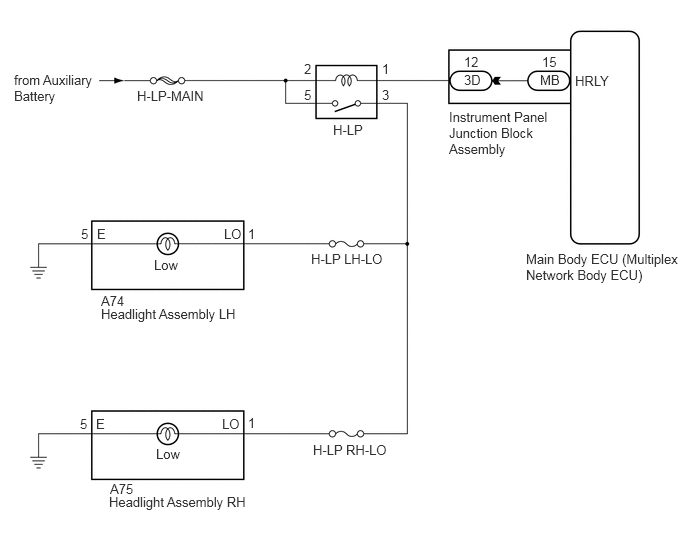
The main body ECU (multiplex network body ECU) controls the low beam headlights.

WIRING DIAGRAM
E220269E14
4.677,1.135 5.802,1.771 1.125,0.635 10 false Instrument Panel Junction Block Assembly 5.479,2.615 7.156,3.083 1.677,0.469 10 false Main Body ECU (Multiplex Network Body ECU) 0.146,0.75 1.042,1.146 0.896,0.396 10 false from Auxiliary Battery 1.427,0.917 2.188,1.24 0.76,0.323 10 false H-LP-MAIN 3.469,1.271 4.083,1.469 0.615,0.198 10 false H-LP 3.24,2.615 4.771,2.813 1.531,0.198 10 false H-LP LH-LO 3.26,4.604 4.792,4.802 1.531,0.198 10 false H-LP RH-LO 1.052,3.188 3.042,3.385 1.99,0.198 10 false Headlight Assembly LH 1.135,5.146 3.125,5.344 1.99,0.198 10 false Headlight Assembly RH 1.052,3.052 1.552,3.302 0.5,0.25 10 false A74 1.146,5.01 1.625,5.26 0.479,0.25 10 false A75 1.604,2.677 2.021,2.896 0.417,0.219 10 false Low 1.625,4.646 2.167,4.854 0.542,0.208 10 false Low 0.844,2.354 1.156,2.552 0.313,0.198 10 false 5 1.01,2.354 1.167,2.552 0.156,0.198 10 false E 1,4.333 1.156,4.531 0.156,0.198 10 false E 0.833,4.333 0.99,4.531 0.156,0.198 10 false 5 2.333,2.354 2.646,2.552 0.313,0.198 10 false LO 2.313,4.333 2.625,4.531 0.313,0.198 10 false LO 2.583,2.354 2.74,2.552 0.156,0.198 10 false 1 2.583,4.323 2.74,4.521 0.156,0.198 10 false 1 3.167,0.635 3.385,0.896 0.219,0.26 10 false 2 3.979,0.635 4.135,0.833 0.156,0.198 10 false 1 3.167,0.906 3.323,1.104 0.156,0.198 10 false 5 3.979,0.906 4.135,1.104 0.156,0.198 10 false 3 4.833,0.75 5.146,0.948 0.313,0.198 10 false 3D 5.625,0.75 5.938,0.948 0.313,0.198 10 false MB 4.833,0.563 5.146,0.76 0.313,0.198 10 false 12 5.646,0.563 5.958,0.76 0.313,0.198 10 false 15 5.99,0.76 6.667,1.01 0.677,0.25 10 false HRLY

CAUTION / NOTICE / HINT

NOTICE:

Inspect the fuses and bulbs for circuits related to this system before performing the following inspection procedure.


PROCEDURE

1.PERFORM ACTIVE TEST USING INTELLIGENT TESTER
a.

Connect the intelligent tester to the DLC3.


b.

Turn the power switch on (IG).


c.

Turn the intelligent tester on.


d.

Enter the following menus: Body / Main Body / Active Test.


e.

Check that the relay operates.

Body Electrical > Main Body > Active Test
Tester Display Measurement Item Control Range Diagnostic Note
Headlight Relay Headlight relay (low beam headlights) ON/OFF -
Body Electrical > Main Body > Active Test
Tester Display
Headlight Relay
50004 123 14
OK:

Headlight relay operates. (Low beam headlights illuminate.)


Result:
Proceed to
OK
NG


OK

PROCEED TO NEXT SUSPECTED AREA SHOWN IN PROBLEM SYMPTOMS TABLE

NG

2.INSPECT H-LP RELAY
a.

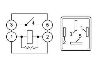
Remove the H-LP relay from the engine room relay block and junction block assembly.

b.
E209495

Measure the resistance according to the value(s) in the table below.

Standard Resistance:
Tester Connection Condition Specified Condition
3 - 5 Voltage not applied between terminals 1 and 2 10 kΩ or higher
3 - 5 Voltage applied between terminals 1 and 2 Below 1 Ω


Result:
Proceed to
OK
NG


OK

3.CHECK HARNESS AND CONNECTOR (H-LP MAIN FUSE - H-LP RELAY)

NG

REPLACE H-LP RELAY

3.CHECK HARNESS AND CONNECTOR (H-LP MAIN FUSE - H-LP RELAY)
a.

Measure the voltage according to the value(s) in the table below.

Standard Voltage:
Tester Connection Condition Specified Condition
Relay Terminal 2 - Body ground Power switch off 11 to 14 V
Relay Terminal 5 - Body ground Power switch off 11 to 14 V


Result:
Proceed to
OK
NG


OK

4.CHECK HARNESS AND CONNECTOR (H-LP RELAY - HEADLIGHT ASSEMBLY LH AND HEADLIGHT ASSEMBLY RH)

NG

REPAIR OR REPLACE HARNESS OR CONNECTOR

4.CHECK HARNESS AND CONNECTOR (H-LP RELAY - HEADLIGHT ASSEMBLY LH AND HEADLIGHT ASSEMBLY RH)
a.

Disconnect the A74 headlight assembly LH connector.


b.

Disconnect the A75 headlight assembly RH connector.


c.

Measure the resistance according to the value(s) in the table below.

Standard Resistance:
Tester Connection Condition Specified Condition
Relay Terminal 3 - A74-1 (LO) Always Below 1 Ω
Relay Terminal 3 - A75-1 (LO) Always Below 1 Ω
Relay Terminal 3 - Body ground Always 10 kΩ or higher


Result:
Proceed to
OK
NG


OK

5.CHECK HARNESS AND CONNECTOR (H-LP RELAY - INSTRUMENT PANEL JUNCTION BLOCK ASSEMBLY)

NG

REPAIR OR REPLACE HARNESS OR CONNECTOR

5.CHECK HARNESS AND CONNECTOR (H-LP RELAY - INSTRUMENT PANEL JUNCTION BLOCK ASSEMBLY)
a.

Disconnect the 3D instrument panel junction block assembly connector.


b.

Measure the resistance according to the value(s) in the table below.

Standard Resistance:
Tester Connection Condition Specified Condition
Relay Terminal 1 - 3D-12 Always Below 1 Ω
Relay Terminal 1 - Body ground Always 10 kΩ or higher


Result:
Proceed to
OK
NG


OK

6.INSPECT INSTRUMENT PANEL JUNCTION BLOCK ASSEMBLY

NG

REPAIR OR REPLACE HARNESS OR CONNECTOR

6.INSPECT INSTRUMENT PANEL JUNCTION BLOCK ASSEMBLY
a.

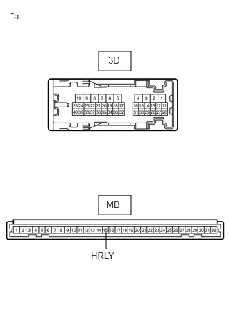
Remove the instrument panel junction block assembly.

Click herePower Source / Network>POWER DISTRIBUTION>MAIN BODY ECU>REMOVAL

b.
E182506C02
1.479,0.771 1.969,1.063 0.49,0.292 1.479,2.938 1.969,3.229 0.49,0.292 1.594,3.49 1.594,3.75 false 0.156,0.156 0.938,0.813 0.781,0.656 10 *a 1.625,0.823 2.427,1.354 0.802,0.531 10 3D 1.594,2.99 2.344,3.458 0.75,0.469 10 MB 1.365,3.76 2.438,4.344 1.073,0.583 10 HRLY
*a Component without harness connected
(Instrument Panel Junction Block Assembly)


Remove the main body ECU (multiplex network body ECU) from the instrument panel junction block assembly.


c.

Measure the resistance according to the value(s) in the table below.

Standard Resistance:
Tester Connection Condition Specified Condition
3D-12 - MB-15 (HRLY) Always Below 1 Ω
3D-12 - Body ground Always 10 kΩ or higher


Result:
Proceed to
OK
NG


OK

REPLACE MAIN BODY ECU (MULTIPLEX NETWORK BODY ECU)

NG

REPLACE INSTRUMENT PANEL JUNCTION BLOCK ASSEMBLY