Home › Audio / Visual / Telematics › PARK ASSIST / MONITORING › TOYOTA PARKING ASSIST-SENSOR SYSTEM(for 2 Sensor Type) › 2012.02–2015.04
RM2040EQ _56 Audio / Visual / Telematics _014718 PARK ASSIST / MONITORING _0076658 TOYOTA PARKING ASSIST-SENSOR SYSTEM(for 2 Sensor Type) J

PARK ASSIST / MONITORING  TOYOTA PARKING ASSIST-SENSOR SYSTEM(for 2 Sensor Type)  Reverse Signal Circuit  


DESCRIPTION

The clearance warning ECU assembly receives a reverse signal from the power management control ECU via the engine room junction block assembly.

WIRING DIAGRAM
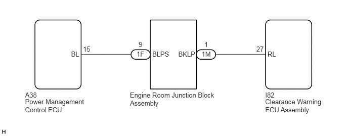
E235272E08
0.516,2.014 1.814,2.347 1.298,0.332 10 Power Management Control ECU 2.676,1.874 4.483,2.206 1.806,0.332 10 Engine Room Junction Block Assembly 0.516,1.874 0.848,2.018 0.332,0.144 10 A38 5.462,2.014 6.760,2.347 1.298,0.332 10 Clearance Warning ECU Assembly 5.462,1.874 5.795,2.018 0.332,0.144 10 I82 1.464,1.031 1.796,1.175 0.332,0.144 10 BL 3.135,1.031 3.515,1.175 0.380,0.144 10 BLPS 3.672,1.031 4.051,1.175 0.380,0.144 10 BKLP 2.813,1.031 3.145,1.175 0.332,0.144 10 1F 2.855,0.836 3.187,0.980 0.332,0.144 10 9 4.152,1.031 4.485,1.175 0.332,0.144 10 1M 4.208,0.836 4.541,0.980 0.332,0.144 10 1 1.709,0.926 2.041,1.070 0.332,0.144 10 15 5.51,1.031 5.843,1.175 0.332,0.144 10 RL 5.279,0.926 5.611,1.070 0.332,0.144 10 27

PROCEDURE

1.CHECK HARNESS AND CONNECTOR (REVERSE SIGNAL)
a.

Disconnect the I82 clearance warning ECU assembly connector.


b.

Measure the voltage according to the value(s) in the table below.

Standard Voltage:
Tester Connection Condition Specified Condition
I82-27 (RL) - Body ground Power switch on (IG)
Shift lever in R
11 to 14 V
I82-27 (RL) - Body ground Power switch on (IG)
Shift lever in any position except R
Below 1 V


Result:
Proceed to
OK
NG


OK

NG

2.CHECK HARNESS AND CONNECTOR (CLEARANCE WARNING ECU ASSEMBLY - ENGINE ROOM JUNCTION BLOCK ASSEMBLY)
a.

Disconnect the 1M engine room junction block assembly connector.


b.

Measure the resistance according to the value(s) in the table below.

Standard Resistance:
Tester Connection Condition Specified Condition
I82-27 (RL) - 1M-1 (BKLP) Always Below 1 Ω
I82-27 (RL) - Body ground Always 10 kΩ or higher


Result:
Proceed to
OK
NG


OK

3.CHECK HARNESS AND CONNECTOR (ENGINE ROOM JUNCTION BLOCK ASSEMBLY - POWER MANAGEMENT CONTROL ECU)

NG

REPAIR OR REPLACE HARNESS OR CONNECTOR

3.CHECK HARNESS AND CONNECTOR (ENGINE ROOM JUNCTION BLOCK ASSEMBLY - POWER MANAGEMENT CONTROL ECU)
a.

Disconnect the 1F engine room junction block assembly connector.


b.

Disconnect the A38 power management control ECU connector.


c.

Measure the resistance according to the value(s) in the table below.

Standard Resistance:
Tester Connection Condition Specified Condition
1F-9 (BLPS) - A38-15 (BL) Always Below 1 Ω
1F-9 (BLPS) - Body ground Always 10 kΩ or higher


Result:
Proceed to
OK
NG


OK

4.REPLACE ENGINE ROOM JUNCTION BLOCK ASSEMBLY

NG

REPAIR OR REPLACE HARNESS OR CONNECTOR

4.REPLACE ENGINE ROOM JUNCTION BLOCK ASSEMBLY
a.

Replace the engine room junction block assembly with a new one or known good one.

Click herePower Source / Network>POWER DISTRIBUTION>INTEGRATION RELAY>REMOVAL


b.

Check that the malfunction disappears.

OK:

Malfunction disappears.


Result:
Proceed to
OK
NG


OK

END (ENGINE ROOM JUNCTION BLOCK ASSEMBLY WAS DEFECTIVE)

NG