Home › Audio / Visual / Telematics › PARK ASSIST / MONITORING › BLIND SPOT MONITOR SYSTEM › 2012.02–2015.04
RM2040EQ _56 Audio / Visual / Telematics _014718 PARK ASSIST / MONITORING _0075026 BLIND SPOT MONITOR SYSTEM C

PARK ASSIST / MONITORING  BLIND SPOT MONITOR SYSTEM  C1AB5  Open in Outer Mirror Indicator(Slave)  


DESCRIPTION

This DTC is stored when the blind spot monitor sensor LH detects an open in the outer rear view mirror indicator LH.

DTC No. Detection Item DTC Detection Condition Trouble Area
C1AB5 Open in Outer Mirror Indicator(Slave)
Both of the following conditions are met:
·

Blind spot monitor main switch (warning canceling switch assembly) is on.


·

The current flowing to the indicator is below a specified value when indicator operation voltage is being sent to the indicator.


·

Outer rear view mirror LH

·

Mirror sub-assembly LH

·

Wire harness or connector

·

Blind spot monitor sensor LH

·

Outer mirror control ECU assembly LH


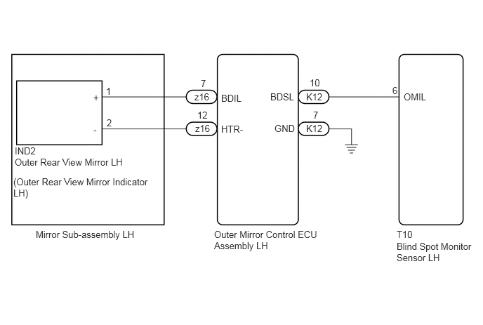
WIRING DIAGRAM

E233743E40
1.573,1.271 1.708,1.427 0.135,0.156 10 false 1 2.979,1.156 3.115,1.313 0.135,0.156 10 false 7 5.823,1.26 5.948,1.417 0.125,0.156 10 false 6 3.281,1.375 3.688,1.531 0.406,0.156 10 false BDIL 5.99,1.354 6.396,1.51 0.406,0.156 10 false OMIL 3.281,1.833 3.646,1.99 0.365,0.156 10 false HTR- 0.219,2.156 0.594,2.313 0.375,0.156 10 false IND2 5.885,3.396 6.333,3.552 0.448,0.156 10 false T10 1.385,1.365 1.521,1.521 0.135,0.156 10 false + 1.385,1.844 1.521,2 0.135,0.156 10 false - 1.583,1.74 1.719,1.896 0.135,0.156 10 false 2 2.927,1.625 3.125,1.781 0.198,0.156 10 false 12 0.219,2.323 2.354,2.49 2.135,0.167 10 false Outer Rear View Mirror LH 0.531,3.396 2.135,3.75 1.604,0.354 10 false Mirror Sub-assembly LH 5.885,3.573 7.083,3.885 1.198,0.313 10 false Blind Spot Monitor Sensor LH 0.198,2.615 2.281,2.927 2.083,0.313 10 false (Outer Rear View Mirror Indicator LH) 2.885,1.354 3.323,1.542 0.438,0.188 10 false z16 2.896,1.823 3.417,2.135 0.521,0.313 10 false z16 3.177,3.396 4.75,3.76 1.573,0.365 10 false Outer Mirror Control ECU Assembly LH 4.01,1.354 4.656,1.75 0.646,0.396 10 false BDSL 4.073,1.823 4.438,1.979 0.365,0.156 10 false GND 4.594,1.146 4.781,1.302 0.188,0.156 10 false 10 4.646,1.625 4.781,1.781 0.135,0.156 10 false 7 4.542,1.354 4.823,1.51 0.281,0.156 10 false K12 4.542,1.823 4.875,1.979 0.333,0.156 10 false K12

CAUTION / NOTICE / HINT

NOTICE:

When checking for DTCs, make sure that the blind spot monitor main switch (warning canceling switch assembly) is on.


PROCEDURE

1.CHECK DTC
a.

Clear the DTCs.

Click hereAudio / Visual / Telematics>PARK ASSIST / MONITORING>BLIND SPOT MONITOR SYSTEM>DTC CHECK / CLEAR

Body Electrical > Blind Spot Monitor Slave > Clear DTCs
50002 314

b.

Recheck for DTCs and check if the same DTC is output again.

Body Electrical > Blind Spot Monitor Slave > Trouble Codes
50001 314
OK:

No DTCs are output.


Result:
Proceed to
OK
NG


OK

NG

2.CHECK HARNESS AND CONNECTOR (OUTER MIRROR CONTROL ECU ASSEMBLY LH - BLIND SPOT MONITOR SENSOR LH)
a.

Disconnect connector T10 from the blind spot monitor sensor LH.


b.

Disconnect connector K12 from the outer mirror control ECU assembly LH.

c.

Measure the resistance according to the value(s) in the table below.

Standard Resistance:
Tester Connection Condition Specified Condition
T10-6 (OMIL) - K12-10 (BDSL) Always Below 1 Ω
K12-7 (GND) - Body ground Always Below 1 Ω


Result:
Proceed to
OK
NG


OK

3.INSPECT OUTER REAR VIEW MIRROR LH (OUTER REAR VIEW MIRROR INDICATOR LH)

NG

REPAIR OR REPLACE HARNESS OR CONNECTOR

3.INSPECT OUTER REAR VIEW MIRROR LH (OUTER REAR VIEW MIRROR INDICATOR LH)
a.

Disconnect connector z16 from the outer mirror control ECU assembly LH.

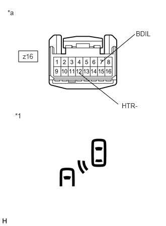
b.
E233726C03
0.385,1.052 0.781,1.281 0.396,0.229 2.104,1.281 2.792,0.708 false 1.635,1.51 2.448,2.156 false 0.156,0.177 0.438,0.396 0.281,0.219 10 false *a 0.313,2.313 0.594,2.531 0.281,0.219 10 false *1 0.469,1.083 0.896,1.417 0.427,0.333 10 false z16 2.813,0.615 3.406,0.885 0.594,0.271 10 false BDIL 2.521,2.104 3.146,2.469 0.625,0.365 10 false HTR-
*1 Outer Rear View Mirror Indicator LH
*a Component without harness connected
(Mirror Sub-assembly LH)


Check that the outer rear view mirror indicator turns on.

NOTICE:

Do not apply a voltage of more than 6 V.


i.

Connect 4 new 1.5 V dry-cell batteries in series.


ii.

Apply 6 V battery voltage to the terminals of the connector, and check that the outer rear view mirror indicator comes on.

OK:
Connection Specified Condition
6 V battery positive (+) → z16-7 (BDIL)
6 V battery negative (-) → z16-12 (HTR-)
Indicator turns on


Result:
Proceed to
OK
NG


OK

4.INSPECT OUTER MIRROR CONTROL ECU ASSEMBLY LH

NG

5.CHECK HARNESS AND CONNECTOR (MIRROR SUB-ASSEMBLY LH - OUTER MIRROR CONTROL ECU ASSEMBLY LH)
4.INSPECT OUTER MIRROR CONTROL ECU ASSEMBLY LH
a.

Disconnect connector K12 from the outer mirror control ECU assembly LH.


b.
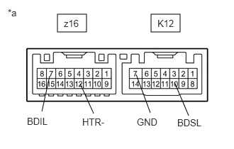
E233744C29
2.219,0.208 2.646,0.469 0.427,0.26 0.844,0.208 1.271,0.469 0.427,0.26 2.563,1.208 2.771,1.698 false 2,1.094 2.208,1.656 false 1.177,1.229 1.375,1.667 false 0.729,1.115 0.615,1.635 false 2.313,0.26 2.698,0.51 0.385,0.25 10 false K12 2.604,1.719 3.083,1.917 0.479,0.198 10 false BDSL 0.115,0.104 0.313,0.302 0.198,0.198 10 false *a 0.938,0.26 1.542,0.667 0.604,0.406 10 false z16 2.01,1.708 2.479,1.958 0.469,0.25 10 false GND 1.208,1.708 1.688,1.906 0.479,0.198 10 false HTR- 0.396,1.698 0.958,2.052 0.563,0.354 10 false BDIL
*a Component without harness connected
(Outer Mirror Control ECU Assembly LH)


Measure the resistance according to the value(s) in the table below.

Standard Resistance:
Tester Connection Condition Specified Condition
K12-10 (BDSL) - z16-7 (BDIL) Always Below 1 Ω
K12-7 (GND) - z16-12 (HTR-) Always Below 1 Ω


Result:
Proceed to
OK
NG


OK

NG

REPLACE OUTER MIRROR CONTROL ECU ASSEMBLY LH

5.CHECK HARNESS AND CONNECTOR (MIRROR SUB-ASSEMBLY LH - OUTER MIRROR CONTROL ECU ASSEMBLY LH)
a.

Disconnect connector IND2 from the outer rear view mirror LH.


b.

Measure the resistance according to the value(s) in the table below.

Standard Resistance:
Tester Connection Condition Specified Condition
z16-7 (BDIL) - IND2-1 (+) Always Below 1 Ω
z16-12 (HTR-) - IND2-2 (-) Always Below 1 Ω


Result:
Proceed to
OK
NG


OK

REPLACE OUTER REAR VIEW MIRROR LH (OUTER REAR VIEW MIRROR INDICATOR LH)

NG

REPLACE MIRROR SUB-ASSEMBLY LH