PRE-CRASH SAFETY PRE-CRASH SAFETY SYSTEM Pre-crash Safety System Circuit
DESCRIPTION
This circuit provides power to operate the driving support ECU assembly.
WIRING DIAGRAM
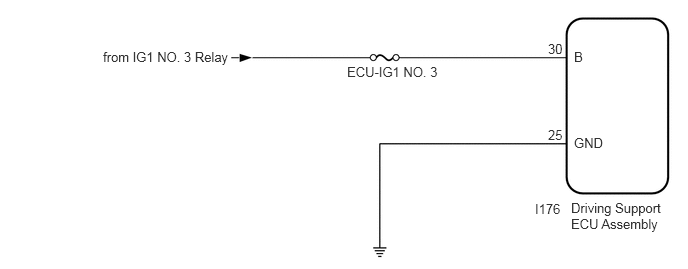
PROCEDURE
Check the customer problem analysis and symptom.
- Result:
Proceed to NEXT
NEXT
Measure the auxiliary battery voltage with the power switch off.
- Standard Voltage:
11 to 14 V
Using the parts location and system diagram, check the system for blown-out fuses, open or short circuits in the wire harness(es) and connectors that are not properly connected by performing a visual check.
- HINT:
-
If the voltage is 11 V or less, replace or recharge the auxiliary battery before proceeding to the next step.
- Result:
Proceed to NEXT
NEXT
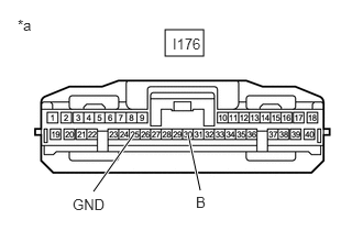
| *a | Front view of wire harness connector
(to Driving Support ECU Assembly) |
Check driving support ECU assembly.
- NOTICE:
-
As the connector may be damaged if a load of more than 10 kg (22 lb) is applied to it, do not apply any more load than necessary to the connector.
Disconnect the I176 driving support ECU assembly connector.
Measure the voltage according to the value(s) in the table below.
- NOTICE:
-
DTCs may be output when connectors are disconnected during inspection. Therefore, make sure to clear the DTCs using the GTS once the inspection has been completed.
- Standard Voltage:
Tester Connection Condition Specified Condition I176-30 (B) - Body ground Power switch on (IG) 11 to 14 V I176-30 (B) - Body ground Power switch off Below 1 V
Measure the resistance according to the value(s) in the table below.
- Standard Resistance:
Tester Connection Condition Specified Condition I176-25 (GND) - Body ground Always Below 1 Ω
- Result:
Proceed to OK NG
OK
NG
- NOTICE:
-
Before checking the millimeter wave radar sensor assembly beam axis deviation, check the installation condition of the millimeter wave radar sensor assembly.
Adjust the reflector height.
Click hereEngine / Hybrid System>CRUISE CONTROL>MILLIMETER WAVE RADAR SENSOR>ADJUSTMENT
Place the reflector.
Click hereEngine / Hybrid System>CRUISE CONTROL>MILLIMETER WAVE RADAR SENSOR>ADJUSTMENT
Connect the GTS to the DLC3.
Turn the GTS on.
Turn the cruise control switch (ON/OFF button) on.
Enter the following menus: Powertrain / Radar Cruise / Utility / Beam Axis Misalignment Reading.
Check the amount of misalignment and make a note.
- Powertrain > Radar Cruise > Utility
-
Tester Display Beam Axis Misalignment Reading - 50005 197 4260
- Result:
Result Proceed to There is no beam axis misalignment A There is a beam axis misalignment B
A
B
Use the GTS to check if the CAN communication system is functioning normally.
- Result:
Result Proceed to CAN communication system DTCs are not output A CAN communication system DTCs are output B
A
B
Click herePower Source / Network>NETWORKING>CAN COMMUNICATION SYSTEM>HOW TO PROCEED WITH TROUBLESHOOTING
Check for DTCs and note any codes that are output.
Click hereVehicle Interior>PRE-CRASH SAFETY>PRE-CRASH SAFETY SYSTEM>DTC CHECK / CLEAR
- Body Electrical > Pre-Crash 2 > Trouble Codes
- 50001 220
Clear the DTCs.
Click hereVehicle Interior>PRE-CRASH SAFETY>PRE-CRASH SAFETY SYSTEM>DTC CHECK / CLEAR
- Body Electrical > Pre-Crash 2 > Clear DTCs
- 50002 220
Recheck for DTCs. Try to reproduce the DTCs by duplicating the conditions indicated by the DTCs.
Click hereVehicle Interior>PRE-CRASH SAFETY>PRE-CRASH SAFETY SYSTEM>DTC CHECK / CLEAR
- Body Electrical > Pre-Crash 2 > Trouble Codes
- 50001 220
- Result:
Result Proceed to DTCs are not output A DTCs are output B
A
B
Using the GTS, check the Data List.
Click hereVehicle Interior>PRE-CRASH SAFETY>PRE-CRASH SAFETY SYSTEM>DATA LIST / ACTIVE TEST
Using the GTS, perform the Active Test.
Click hereVehicle Interior>PRE-CRASH SAFETY>PRE-CRASH SAFETY SYSTEM>DATA LIST / ACTIVE TEST
- Result:
Proceed to NEXT
NEXT