Home › Audio / Visual / Telematics › NAVIGATION / MULTI INFO DISPLAY › NAVIGATION SYSTEM(for SD) › from 2014.05
RM2040EQ _56 Audio / Visual / Telematics _014717 NAVIGATION / MULTI INFO DISPLAY _0169499 NAVIGATION SYSTEM(for SD) J

NAVIGATION / MULTI INFO DISPLAY  NAVIGATION SYSTEM(for SD)  Steering Pad Switch Circuit  


DESCRIPTION

This circuit sends an operation signal from the steering pad switch assembly to the navigation receiver assembly.

If there is an open in the circuit, the audio system cannot be operated using the steering pad switch assembly.

If there is a short in the circuit, the same condition as when a switch is continuously depressed occurs.

Therefore, the navigation receiver assembly cannot be operated using the steering pad switch assembly, and the navigation receiver assembly itself will not function.

WIRING DIAGRAM
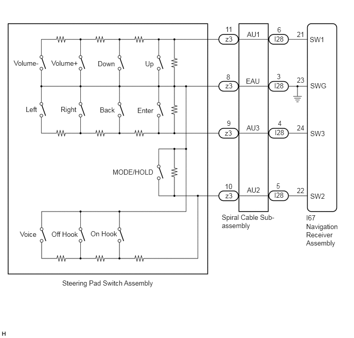
E309444E02
0.281,1.198 1.354,1.396 1.073,0.198 10 false Volume- 1.042,1.198 2.115,1.396 1.073,0.198 10 false Volume+ 1.979,1.208 3.052,1.406 1.073,0.198 10 false Down 2.938,1.208 4.01,1.406 1.073,0.198 10 false Up 0.521,2.135 1.594,2.333 1.073,0.198 10 false Left 1.229,2.135 2.302,2.333 1.073,0.198 10 false Right 2.021,2.146 3.094,2.344 1.073,0.198 10 false Back 2.781,2.156 3.854,2.354 1.073,0.198 10 false Enter 2.281,3.406 3.354,3.604 1.073,0.198 10 false MODE/HOLD 1.042,4.667 2.115,4.865 1.073,0.198 10 false Off Hook 0.406,4.667 1.479,4.865 1.073,0.198 10 false Voice 1.833,4.656 2.906,4.854 1.073,0.198 10 false On Hook 1.26,5.656 3.76,5.854 2.5,0.198 10 false Steering Pad Switch Assembly 4.563,0.708 5.635,0.906 1.073,0.198 10 false z3 4.563,1.656 5.635,1.854 1.073,0.198 10 false z3 4.552,2.615 5.625,2.813 1.073,0.198 10 false z3 4.563,3.885 5.635,4.083 1.073,0.198 10 false z3 4.552,3.698 5.625,3.896 1.073,0.198 10 false 10 4.594,2.417 5.667,2.615 1.073,0.198 10 false 9 4.583,1.479 5.656,1.677 1.073,0.198 10 false 8 4.563,0.51 5.635,0.708 1.073,0.198 10 false 11 5,0.615 6.073,0.813 1.073,0.198 10 false AU1 4.979,1.563 6.052,1.76 1.073,0.198 10 false EAU 4.99,2.51 6.063,2.708 1.073,0.198 10 false AU3 5,3.771 6.073,3.969 1.073,0.198 10 false AU2 5.552,0.708 6.625,0.906 1.073,0.198 10 false I28 5.552,1.656 6.625,1.854 1.073,0.198 10 false I28 5.563,2.604 6.635,2.802 1.073,0.198 10 false I28 5.552,3.875 6.625,4.073 1.073,0.198 10 false I28 5.594,3.688 6.667,3.885 1.073,0.198 10 false 5 5.625,2.417 6.698,2.615 1.073,0.198 10 false 4 5.604,1.469 6.677,1.667 1.073,0.198 10 false 3 5.615,0.521 6.688,0.719 1.073,0.198 10 false 6 6.271,0.719 7.115,0.927 0.844,0.208 10 false SW1 6.281,1.656 7.156,1.885 0.875,0.229 10 false SWG 6.281,2.625 7.156,2.854 0.875,0.229 10 false SW3 6.281,3.896 7.156,4.125 0.875,0.229 10 false SW2 6.01,0.615 7.156,0.813 1.146,0.198 10 false 21 6.01,1.542 7.156,1.74 1.146,0.198 10 false 23 6.01,2.51 7.156,2.708 1.146,0.198 10 false 24 6.01,3.781 7.156,3.979 1.146,0.198 10 false 22 4.49,4.323 5.604,4.781 1.115,0.458 10 false Spiral Cable Sub-assembly 6.198,4.51 6.854,5.177 0.656,0.667 10 false Navigation Receiver Assembly 6.198,4.333 6.698,4.552 0.5,0.219 10 false I67

CAUTION / NOTICE / HINT

NOTICE:

The vehicle is equipped with a Supplemental Restraint System (SRS) which includes components such as airbags. Before servicing (including removal or installation of parts), be sure to read the precaution for Supplemental Restraint System.

Click hereVehicle Interior>SUPPLEMENTAL RESTRAINT SYSTEMS>AIRBAG SYSTEM>PRECAUTION


PROCEDURE

1.CHECK HARNESS AND CONNECTOR (STEERING PAD SWITCH SIGNAL)
a.

Disconnect the I67 navigation receiver assembly connector.


b.

Measure the resistance according to the value(s) in the table below.
Standard Resistance:
Tester Connection Condition Specified Condition
I67-21 (SW1) - I67-23 (SWG) No switch pushed 95 to 105 kΩ
Up switch pushed Below 2.5 Ω
Down switch pushed 313 to 345 Ω
Volume+ switch pushed 950 to 1050 Ω
Volume- switch pushed 2955 to 3265 Ω
I67-22 (SW2) - I67-23 (SWG) No switch pushed 95 to 105 kΩ
MODE/HOLD switch pushed Below 2.5 Ω
On hook switch pushed 313 to 345 Ω
Off hook switch pushed 950 to 1050 Ω
Voice switch pushed 2955 to 3265 Ω
I67-24 (SW3) - I67-23 (SWG) No switch pushed 95 to 105 kΩ
Enter switch pushed Below 2.5 Ω
Back switch pushed 313 to 345 Ω
Right switch pushed 950 to 1050 Ω
Left switch pushed 2955 to 3265 Ω


Result:
Proceed to
OK
NG


OK

PROCEED TO NEXT SUSPECTED AREA SHOWN IN PROBLEM SYMPTOMS TABLE

NG

2.INSPECT STEERING PAD SWITCH ASSEMBLY
a.

Remove the steering pad switch assembly.

Click hereSteering>STEERING COLUMN>STEERING PAD SWITCH>REMOVAL


b.

Measure the resistance according to the value(s) in the table below.

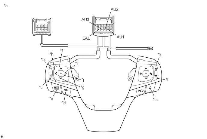
E309446C01
3.125,1.24 3.417,1.021 false 3.083,0.76 3.521,1.01 false 3.833,0.417 3.635,1.01 false 4.021,1.219 3.74,1.021 false 2.135,1.865 2.052,2.333 false 2.604,2.25 2.292,2.479 false 2.792,2.76 2.146,2.594 false 2.771,3.01 2.146,2.74 false 2.271,3.188 2.229,3.458 false 1.969,3.125 1.833,3.344 false 1.76,2.708 1.479,2.958 false 1.771,2.313 1.542,2.135 false 1.802,1.969 1.906,2.469 false 5.51,1.99 5.385,2.302 false 5.708,2.76 5.375,2.708 false 5.333,3.333 5.24,3.115 false 0.135,0.115 0.448,0.271 0.313,0.156 10 false *a 1.417,1.979 1.729,2.177 0.313,0.198 10 false *b 1.354,2.948 1.667,3.104 0.313,0.156 10 false *c 2.146,3.479 2.458,3.635 0.313,0.156 10 false *d 1.708,3.333 2.021,3.49 0.313,0.156 10 false *e 2.083,1.677 2.406,1.885 0.323,0.208 10 false *f 2.792,2.938 3.125,3.24 0.333,0.302 10 false *g 1.719,1.792 2.042,1.979 0.323,0.188 10 false *h 2.604,2.125 2.917,2.417 0.313,0.292 10 false *i 2.823,2.677 3.125,2.906 0.302,0.229 10 false *j 5.469,1.813 5.781,1.969 0.313,0.156 10 false *k 5.74,2.688 6.052,2.969 0.313,0.281 10 false *l 5.292,3.365 5.604,3.573 0.313,0.208 10 false *m 2.854,1.24 3.396,1.448 0.542,0.208 10 false EAU 2.823,0.594 3.365,0.802 0.542,0.208 10 false AU3 3.833,0.24 4.375,0.448 0.542,0.208 10 false AU2 4.042,1.198 4.583,1.406 0.542,0.208 10 false AU1
*a Component without harness connected
(Steering Pad Switch Assembly)
*b Volume+
*c Volume- *d Back
*e MODE/HOLD *f Up
*g Down *h Left
*i Right *j Enter
*k Off hook *l On hook
*m Voice - -


Standard Resistance:
Tester Connection Condition Specified Condition
11 (AU1) - 8 (EAU) No switch pushed 95 to 105 kΩ
Up switch pushed Below 2.5 Ω
Down switch pushed 313 to 345 Ω
Volume+ switch pushed 950 to 1050 Ω
Volume- switch pushed 2955 to 3265 Ω
10 (AU2) - 8 (EAU) No switch pushed 95 to 105 kΩ
MODE/HOLD switch pushed Below 2.5 Ω
On hook switch pushed 313 to 345 Ω
Off hook switch pushed 950 to 1050 Ω
Voice switch pushed 2955 to 3265 Ω
9 (AU3) - 8 (EAU) No switch pushed 95 to 105 kΩ
Enter switch pushed Below 2.5 Ω
Back switch pushed 313 to 345 Ω
Right switch pushed 950 to 1050 Ω
Left switch pushed 2955 to 3265 Ω


Result:
Proceed to
OK
NG


OK

3.INSPECT SPIRAL CABLE SUB-ASSEMBLY

NG

REPLACE STEERING PAD SWITCH ASSEMBLY

3.INSPECT SPIRAL CABLE SUB-ASSEMBLY
a.

Remove the spiral cable sub-assembly.

Click hereVehicle Interior>SUPPLEMENTAL RESTRAINT SYSTEMS>SPIRAL CABLE>REMOVAL
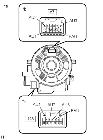

b.
E268445C39
1.604,0.313 1.896,0.5 0.292,0.188 0.865,3.875 1.188,4.073 0.323,0.198 1.229,1.167 1.583,1.031 false 1.698,1.031 1.24,0.635 false 2.25,1.188 1.896,1.021 false 2.323,3.719 1.844,3.979 false 1.656,3.99 1.729,3.583 false 1.552,3.99 1.333,3.573 false 1.802,1.01 2.281,0.719 false 2.104,3.583 1.76,3.99 false 0.135,0.115 0.448,0.313 0.313,0.198 10 false *a 0.75,0.219 1.063,0.417 0.313,0.198 10 false *b 1.667,0.313 1.979,0.51 0.313,0.198 10 false z3 0.958,1.125 1.292,1.323 0.333,0.198 10 false AU1 0.958,0.5 1.292,0.698 0.333,0.198 10 false AU2 2.292,1.135 2.625,1.333 0.333,0.198 10 false EAU 0.74,3.313 1.052,3.51 0.313,0.198 10 false *c 0.938,3.885 1.25,4.083 0.313,0.198 10 false I28 2.365,3.615 2.698,3.813 0.333,0.198 10 false EAU 1.583,3.417 1.917,3.615 0.333,0.198 10 false AU2 1.094,3.406 1.427,3.604 0.333,0.198 10 false AU1 2.313,0.604 2.781,0.802 0.469,0.198 10 false AU3 2.063,3.417 2.521,3.594 0.458,0.177 10 false AU3
*a Component without harness connected
(Spiral Cable Sub-assembly)
*b Steering Pad Switch Assembly Side
*c Vehicle Side


Measure the resistance according to the value(s) in the table below.

Standard Resistance:
Tester Connection Condition Specified Condition
z3-8 (EAU) - I28-3 (EAU) Center 3 Ω or less
2.5 rotations to the left
2.5 rotations to the right
z3-11 (AU1) - I28-6 (AU1) Center 3 Ω or less
2.5 rotations to the left
2.5 rotations to the right
z3-10 (AU2) - I28-5 (AU2) Center 3 Ω or less
2.5 rotations to the left
2.5 rotations to the right
z3-9 (AU3) - I28-4 (AU3) Center 3 Ω or less
2.5 rotations to the left
2.5 rotations to the right


c.

After setting the spiral cable sub-assembly to the center position, rotate the spiral cable sub-assembly 2.5 times clockwise. Then while rotating the spiral cable sub-assembly 5 times counterclockwise, measure the resistance according to the value(s) in the table below.

Standard Resistance:
Tester Connection Condition Specified Condition
z3-8 (EAU) - I28-3 (EAU) Always 3 Ω or less
z3-11 (AU1) - I28-6 (AU1) Always 3 Ω or less
z3-10 (AU2) - I28-5 (AU2) Always 3 Ω or less
z3-9 (AU3) - I28-4 (AU3) Always 3 Ω or less


NOTICE:
·

Press and hold the lock located in the center of the spiral cable sub-assembly to rotate the spiral cable sub-assembly.

·

The spiral cable sub-assembly is an important part of the SRS airbag system. Incorrect removal or installation of the spiral cable sub-assembly may prevent the airbag from deploying.

·

As the spiral cable sub-assembly may break, do not rotate the spiral cable sub-assembly more than the specified amount.


Result:
Proceed to
OK
NG


OK

REPAIR OR REPLACE HARNESS OR CONNECTOR (SPIRAL CABLE SUB-ASSEMBLY - NAVIGATION RECEIVER ASSEMBLY, BODY GROUND)

NG

REPLACE SPIRAL CABLE SUB-ASSEMBLY