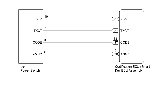
DTC B2784 Antenna Coil Open / Short |
| DTC Code | DTC Detection Condition | Trouble Area | DTC Output Confirmation Operation |
| B2784 | The transponder key amplifier coil built into the power switch is open (see below) or shorted (determined by communication with certification ECU (smart key ECU assembly)) (1 trip detection logic*).
|
| With the shift lever in P, the key held near the power switch and a hybrid control system start operation is performed by pressing and holding the power switch when the key battery is depleted. |
| Vehicle Condition when Malfunction Detected | Fail-safe Operation when Malfunction Detected |
| Hybrid control system cannot be started when key battery is depleted by holding key near power switch and pressing and holding power switch with shift lever in P | - |
| DTC Code | Data List and Active Test |
| B2784 | - |
| 1.CLEAR DTC |
Clear the DTCs (Click here).
| NEXT | |
 |
| 2.CHECK DTC OUTPUT |
Check for DTCs (Click here).
|
| ||||
| OK | ||
 | ||
| ||
| 3.CHECK POWER SWITCH (OUTPUT) |
Using an oscilloscope, check the waveform.
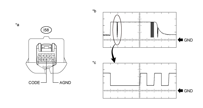
| *a | Component with harness connected (Power Switch) | *b | Waveform |
| *c | Waveform (detail) | - | - |
| Tester Connection | Condition | Tool Setting | Specified Condition |
| I58-5 (CODE) - I58-6 (AGND) | Power switch off, power switch pressed with key held near power switch* | 1 V/DIV., 20 ms/.DIV. | Pulse generation (See waveform) |
| 2 V/DIV.,100 μs/.DIV. | Pulse generation (See waveform (detail)) |
|
| ||||
| OK | |
|
| 4.REPLACE CERTIFICATION ECU (SMART KEY ECU ASSEMBLY) |
Replace the certification ECU (smart key ECU assembly) with a new one.
| NEXT | |
|
| 5.REGISTER ECU COMMUNICATION ID |
Register the ECU communication ID.
| NEXT | |
|
| 6.CLEAR DTC |
Clear the DTCs (Click here).
| NEXT | |
|
| 7.CHECK FOR DTC |
Perform "DTC Output Confirmation Operation" procedure.
Check for DTCs (Click here).
|
| ||||
| OK | ||
| ||
| ||

