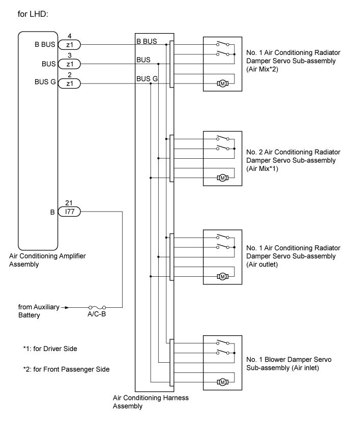
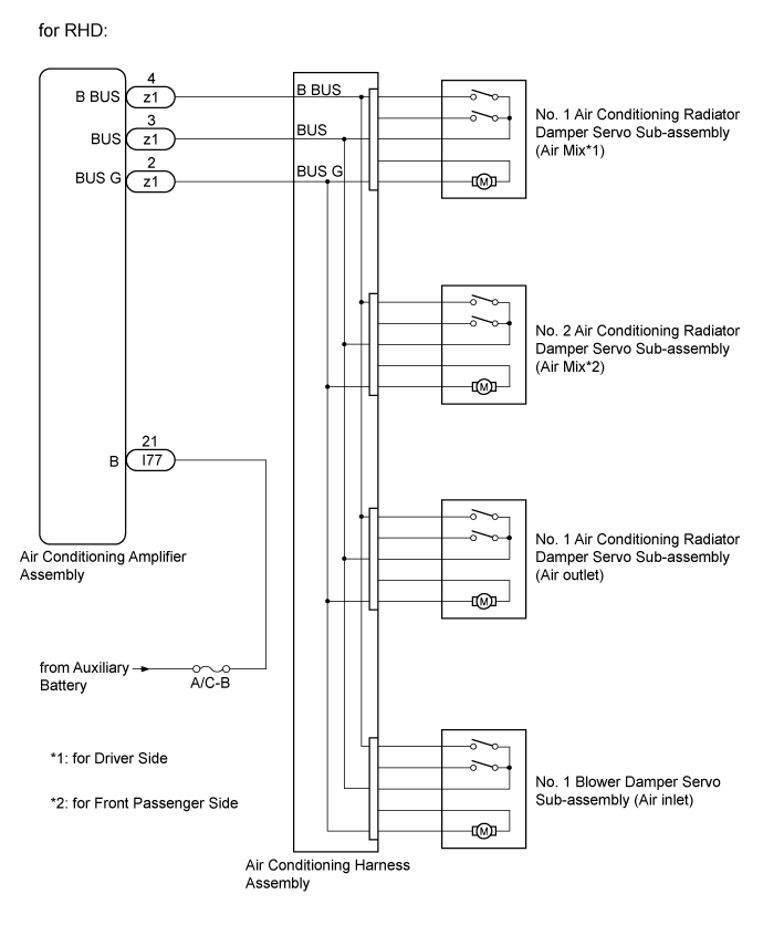
DTC B1497/97 BUS IC Communication Malfunction |
| DTC No. | DTC Detection Condition | Trouble Area |
| B1497/97 | Error or open in communication line |
|
| 1.CONFIRM MODEL |
| Result | Proceed to |
| for LHD | A |
| for RHD | B |
|
| ||||
| A | |
 |
| 2.PERFORM ACTIVE TEST USING INTELLIGENT TESTER |
Connect the intelligent tester to the DLC3.
Turn the power switch on (IG).
Turn the intelligent tester on.
Enter the following menus: Body / Air Conditioner / Active test.
Check the operation by referring to the table below.
| Tester Display | Test Part | Control Range | Diagnostic Note |
| Air Mix Servo Targ Pulse(D) | No. 2 air conditioning radiator damper servo sub-assembly (air mix for driver side) pulse | Min.: 0, Max.: 255 | Operates between 5 and 103 pulses |
| Air Mix Servo Targ Pulse(P) | No. 1 air conditioning radiator damper servo sub-assembly (air mix for front passenger side) pulse | Min.: 0, Max.: 255 | Operates between 7 and 105 pulses |
| Air Inlet Damper Targ Pulse | No. 1 blower damper servo sub-assembly (air inlet) pulse | Min.: 0, Max.: 255 | Operates between 7 and 28 pulses |
| Air Outlet Servo Pulse (D) | No. 1 air conditioning radiator damper servo sub-assembly (air outlet) pulse | Min.: 0, Max.: 255 | Operates between 8 and 97 pulses |
According to the test result, proceed to the next step.
| Result | Proceed to |
| One of the damper servo motors is malfunctioning | A |
| All of the damper servo motors are malfunctioning | B |
|
| ||||
| A | |
|
| 3.SYSTEM CHECK |
According to the test result, proceed to the next step.
| Result | Proceed to |
| Only the No. 2 air conditioning radiator damper servo sub-assembly (air mix for driver side) is malfunctioning | A |
| Only the No. 1 air conditioning radiator damper servo sub-assembly (air mix for front passenger side) is malfunctioning | B |
| Only the No. 1 blower damper servo sub-assembly (air inlet) is malfunctioning | C |
| Only the No. 1 air conditioning radiator damper servo sub-assembly (air outlet) is malfunctioning | D |
|
| ||||
|
| ||||
|
| ||||
| A | |
|
| 4.REPLACE NO. 2 AIR CONDITIONING RADIATOR DAMPER SERVO SUB-ASSEMBLY (AIR MIX FOR DRIVER SIDE) |
Replace the No. 2 air conditioning radiator damper servo sub-assembly (air mix for driver side) (Click here).
Check for the DTC.
| Result | Proceed to |
| DTC B1497/97 is not output | A |
| DTC B1497/97 is output | B |
|
| ||||
| A | ||
 | ||
| ||
| 5.REPLACE NO. 1 AIR CONDITIONING RADIATOR DAMPER SERVO SUB-ASSEMBLY (AIR MIX FOR FRONT PASSENGER SIDE) |
Replace the No. 1 air conditioning radiator damper servo sub-assembly (air mix for front passenger side) (Click here).
Check for the DTC.
| Result | Proceed to |
| DTC B1497/97 is not output | A |
| DTC B1497/97 is output | B |
|
| ||||
| A | ||
| ||
| ||
| 6.REPLACE NO. 1 BLOWER DAMPER SERVO SUB-ASSEMBLY (AIR INLET) |
Replace the No. 1 blower damper servo sub-assembly (air inlet) (Click here).
Check for the DTC.
| Result | Proceed to |
| DTC B1497/97 is not output | A |
| DTC B1497/97 is output | B |
|
| ||||
| A | ||
| ||
| ||
| 7.REPLACE NO. 1 AIR CONDITIONING RADIATOR DAMPER SERVO SUB-ASSEMBLY (AIR OUTLET) |
Replace the No. 1 air conditioning radiator damper servo sub-assembly (air outlet) (Click here).
Check for the DTC.
| Result | Proceed to |
| DTC B1497/97 is not output | A |
| DTC B1497/97 is output | B |
|
| ||||
| A | ||
| ||
| ||
| 8.PERFORM ACTIVE TEST USING INTELLIGENT TESTER |
Connect the intelligent tester to the DLC3.
Turn the power switch on (IG).
Turn the intelligent tester on.
Enter the following menus: Body / Air Conditioner / Active test.
Check the operation by referring to the table below.
| Tester Display | Test Part | Control Range | Diagnostic Note |
| Air Mix Servo Targ Pulse(D) | No. 1 air conditioning radiator damper servo sub-assembly (air mix for driver side) pulse | Min.: 0, Max.: 255 | Operates between 7 and 105 pulses |
| Air Mix Servo Targ Pulse(P) | No. 2 air conditioning radiator damper servo sub-assembly (air mix for front passenger side) pulse | Min.: 0, Max.: 255 | Operates between 5 and 103 pulses |
| Air Inlet Damper Targ Pulse | No. 1 blower damper servo sub-assembly (air inlet) pulse | Min.: 0, Max.: 255 | Operates between 7 and 28 pulses |
| Air Outlet Servo Pulse (D) | No. 1 air conditioning radiator damper servo sub-assembly (air outlet) pulse | Min.: 0, Max.: 255 | Operates between 8 and 97 pulses |
According to the test result, proceed to the next step.
| Result | Proceed to |
| One of the damper servo motors is malfunctioning | A |
| All of the damper servo motors are malfunctioning | B |
|
| ||||
| A | |
|
| 9.SYSTEM CHECK |
According to the test result, proceed to the next step.
| Result | Proceed to |
| Only the No. 1 air conditioning radiator damper servo sub-assembly (air mix for driver side) is malfunctioning | A |
| Only the No. 2 air conditioning radiator damper servo sub-assembly (air mix for front passenger side) is malfunctioning | B |
| Only the No. 1 blower damper servo sub-assembly (air inlet) is malfunctioning | C |
| Only the No. 1 air conditioning radiator damper servo sub-assembly (air outlet) is malfunctioning | D |
|
| ||||
|
| ||||
|
| ||||
| A | |
|
| 10.REPLACE NO. 1AIR CONDITIONING RADIATOR DAMPER SERVO SUB-ASSEMBLY (AIR MIX FOR DRIVER SIDE) |
Replace the No. 1 air conditioning radiator damper servo sub-assembly (air mix for driver side) (Click here).
Check for the DTC.
| Result | Proceed to |
| DTC B1497/97 is not output | A |
| DTC B1497/97 is output | B |
|
| ||||
| A | ||
| ||
| ||
| 11.REPLACE NO. 2 AIR CONDITIONING RADIATOR DAMPER SERVO SUB-ASSEMBLY (AIR MIX FOR FRONT PASSENGER SIDE) |
Replace the No. 2 air conditioning radiator damper servo sub-assembly (air mix for front passenger side) (Click here).
Check for the DTC.
| Result | Proceed to |
| DTC B1497/97 is not output | A |
| DTC B1497/97 is output | B |
|
| ||||
| A | ||
| ||
| ||
| 12.REPLACE NO. 1 BLOWER DAMPER SERVO SUB-ASSEMBLY (AIR INLET) |
Replace the No. 1 blower damper servo sub-assembly (air inlet) (Click here).
Check for the DTC.
| Result | Proceed to |
| DTC B1497/97 is not output | A |
| DTC B1497/97 is output | B |
|
| ||||
| A | ||
| ||
| ||
| 13.REPLACE NO. 1 AIR CONDITIONING RADIATOR DAMPER SERVO SUB-ASSEMBLY (AIR OUTLET) |
Replace the No. 1 air conditioning radiator damper servo sub-assembly (air outlet) (Click here).
Check for the DTC.
| Result | Proceed to |
| DTC B1497/97 is not output | A |
| DTC B1497/97 is output | B |
|
| ||||
| A | ||
| ||
| ||
| 14.REPLACE AIR CONDITIONING HARNESS ASSEMBLY |
Replace the air conditioning harness assembly (Click here).
Check for the DTC.
| Result | Proceed to |
| DTC B1497/97 is not output | A |
| DTC B1497/97 is output | B |
|
| ||||
| A | ||
| ||
| ||
| 15.CHECK HARNESS AND CONNECTOR (POWER SOURCE CIRCUIT) |
Disconnect the I77 air conditioning amplifier assembly connector.
Measure the voltage according to the value(s) in the table below.
| Tester Connection | Condition | Specified Condition |
| I77-21 (B) - Body ground | Power switch off | 11 to 14 V |
|
| ||||
| OK | ||
| ||
| ||

