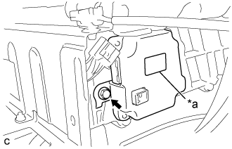
 |
Install the battery smart unit with the bolt.
| *a | Black Label |
- Torque:
- 7.5 N*m{ 76 kgf*cm , 66 in.*lbf }
- NOTICE:
- Check color of the label.
HV BATTERY > INSTALLATION |
| 1. INSTALL NO. 2 HYBRID BATTERY PACK WIRE |
Connect the connector and 5 clamps, and install the No. 2 hybrid battery pack wire.
| 2. INSTALL HYBRID BATTERY JUNCTION BLOCK ASSEMBLY |
Install the hybrid battery junction block assembly with the 3 bolts.
Connect the connector to the hybrid battery junction block assembly.
Using an insulated tool, install the 2 bolts.
Connect the terminal cover.
| 3. INSTALL NO. 1 HYBRID BATTERY SHIELD SUB-ASSEMBLY |
Install the No. 1 hybrid battery shield sub-assembly with the bolt and 3 nuts.
| 4. INSTALL BATTERY SMART UNIT |
|
Install the battery smart unit with the bolt.
| *a | Black Label |
Connect the connector.
| 5. INSTALL NO. 2 HYBRID VEHICLE BATTERY SHIELD PANEL |
Install the No. 2 hybrid vehicle battery shield panel with the 2 bolts and nut.
Connect the 3 wire harness clamps.
Connect the connector.
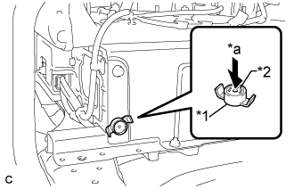 |
Install the battery cover lock striker, then push the button to lock it.
| *1 | Battery Cover Lock Striker |
| *2 | Button |
| *a | Push |
| 6. INSTALL HV BATTERY |
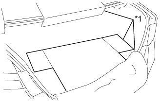 |
Place a piece of cardboard in the luggage compartment.
| *1 | Cardboard |
Using a suitable adaptor such as a rope, install the HV battery to the vehicle in the same direction it was facing during removal.
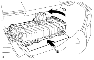 |
Push the cardboard and HV battery together to the middle of the luggage compartment.
| *a | Push |
| *b | Turn 180° |
Turn the cardboard and HV battery 180° together.
Install the battery cooling blower assembly with the 3 nuts.
Connect the connector.
Engage the 2 claws to install the No. 2 hybrid battery intake duct.
Install the clip.
Install the 2 clips.
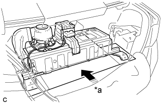 |
Push the HV battery together with the cardboard toward the front of the vehicle.
| *a | Push |
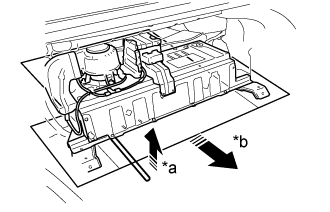 |
Use a tire lever to hold up the HV battery and pull out the cardboard.
| *a | Hold up |
| *b | Pull out |
Remove the luggage compartment floor mat.
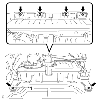 |
Install the HV battery with the 6 bolts.
| *1 | Ground Bolt |
| 7. CONNECT LOW VOLTAGE CONNECTOR |
Connect the 3 connectors.
| 8. CONNECT NO. 4 FLOOR WIRE |
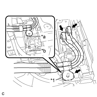 |
Connect the 2 connectors.
| *1 | Shielded Wire Ground |
| *a | Claw |
| *b | Hole |
Connect the shielded wire ground.
| 9. INSTALL NO. 4 HYBRID BATTERY SHIELD PANEL |
Install the No. 4 hybrid battery shield panel with the bolt and 2 nuts.
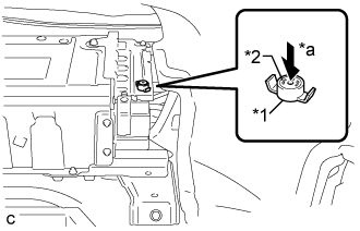 |
Install the battery cover lock striker, then push the button to lock it.
| *1 | Battery Cover Lock Striker |
| *a | Push |
| 10. INSTALL NO. 1 HYBRID BATTERY INTAKE DUCT |
Install the No. 1 hybrid battery intake duct with the 3 clips.
| 11. INSTALL AUXILIARY BATTERY |
Install the auxiliary battery.
Install the auxiliary battery clamp with the bolt and nut.
Connect the auxiliary battery hose.
Connect the positive (+) auxiliary battery cable with the nut.
Install the auxiliary battery terminal cover.
| 12. INSTALL ROOM PARTITION BOARD RH |
Engage the 4 clips to install the room partition board RH.
Install the 4 clips.
| 13. INSTALL ROOM PARTITION BOARD LH |
Engage the 5 claws and clip to install the room partition board LH.
Install the clip.
| 14. INSTALL PACKAGE TRAY TRIM PANEL ASSEMBLY |
Pass the 3 rear seat belt floor anchors through the package tray trim panel assembly.
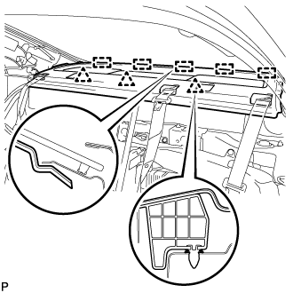 |
Engage the 5 guides and 3 clips to install the package tray trim panel assembly.
| 15. INSTALL REAR SEAT SHOULDER BELT COVER |
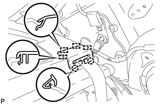 |
Engage the 4 guides and 2 claws to install the rear seat shoulder belt cover.
| 16. INSTALL CENTER STOP LIGHT SET |
Connect the connector.
Temporarily install the center stop light set.
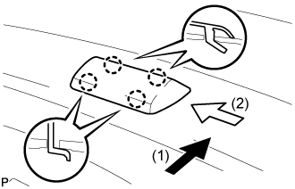 |
Slide the center stop light set in the order and directions shown by the arrows in the illustration while pushing it towards the rear of the vehicle to engage the 4 claws.
| 17. INSTALL ROOF SIDE INNER GARNISH LH |
Engage the guide.
Engage the 5 clips to install the roof side inner garnish LH.
| 18. INSTALL ROOF SIDE INNER GARNISH RH |
| 19. INSTALL REAR DOOR OPENING TRIM WEATHERSTRIP LH |
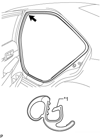 |
Align the alignment mark (Red) on the weatherstrip with the protruding portion on the body indicated by the arrow in the illustration, and install the rear door opening trim weatherstrip LH.
| *1 | Alignment Mark (Red) |
| 20. INSTALL REAR DOOR OPENING TRIM WEATHERSTRIP RH |
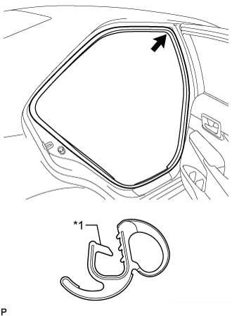 |
Align the alignment mark (Blue) on the weatherstrip with the protruding portion on the body indicated by the arrow in the illustration, and install the rear door opening trim weatherstrip RH.
| *1 | Alignment Mark (Blue) |
| 21. CONNECT REAR SEAT INNER WITH CENTER BELT ASSEMBLY LH |
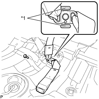 |
Connect the floor anchor of the rear seat inner with center belt assembly LH with the bolt.
| *1 | Protruding Part |
| 22. INSTALL CHILD RESTRAINT SEAT ANCHOR BRACKET SUB-ASSEMBLY LH |
Install the child restraint seat anchor bracket sub-assembly LH with the 2 nuts.
| 23. CONNECT REAR SEAT OUTER BELT ASSEMBLY (for LH Side) |
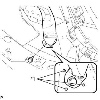 |
Connect the floor anchor of the rear seat outer belt assembly with the bolt.
| *1 | Protruding Part |
| 24. CONNECT REAR SEAT OUTER BELT ASSEMBLY (for RH Side) |
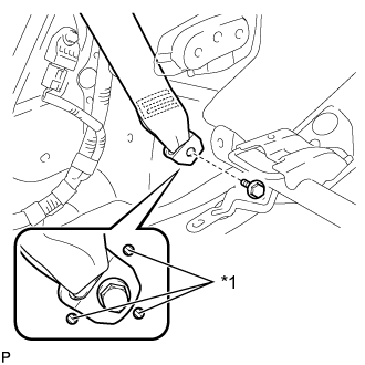 |
Connect the floor anchor of the rear seat outer belt assembly with the bolt.
| *1 | Protruding Part |
| 25. INSTALL REAR SIDE SEATBACK ASSEMBLY LH |
Place the rear side seatback assembly LH in the cabin.
Engage the hook to install the rear side seatback assembly LH with the bolt.
Connect the rear seat outer belt to the rear seat shoulder belt guide LH.
| 26. INSTALL REAR SIDE SEATBACK ASSEMBLY RH |
Place the rear side seatback assembly RH in the cabin.
Engage the hook to install the rear side seatback assembly RH with the bolt.
Connect the rear seat outer belt to the rear seat shoulder belt guide RH.
| 27. INSTALL REAR SEATBACK ASSEMBLY LH |
Place the rear seatback assembly LH in the cabin.
Install the rear seatback assembly LH with the 2 bolts.
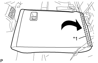 |
Engage the fastener as shown in the illustration.
| *1 | Fastener |
Raise the rear seatback assembly LH.
Connect the rear seat outer belt to the rear seat center shoulder belt guide.
| 28. INSTALL NO. 2 ROOM PARTITION COVER |
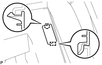 |
Engage the guide and claw to install the No. 2 room partition cover.
| 29. INSTALL REAR SEATBACK ASSEMBLY RH |
Place the rear seatback assembly RH in the cabin.
Install the rear seatback assembly RH with the 2 bolts.
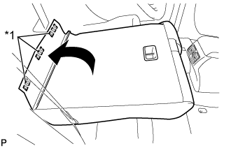 |
Engage the fastener as shown in the illustration.
| *1 | Fastener |
Raise the rear seatback assembly RH.
| 30. INSTALL REAR SEAT CUSHION LOCK HOOK |
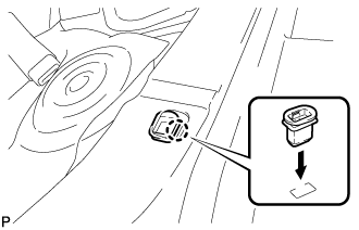 |
Engage the claw to install a new rear seat cushion lock hook.
| 31. INSTALL REAR SEAT CUSHION ASSEMBLY |
Place the rear seat cushion assembly in the cabin.
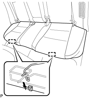 |
Engage the 2 hooks of the rear seat cushion assembly to the vehicle body as shown in the illustration.
Confirm that the rear seat cushion assembly is firmly installed.
| 32. INSTALL REAR SEAT HEADREST ASSEMBLY |
| 33. INSTALL LUGGAGE COMPARTMENT INNER TRIM COVER LH |
Install the 3 clips.
Engage the fastener and install the luggage compartment inner trim cover LH.
| 34. INSTALL LUGGAGE COMPARTMENT INNER TRIM COVER RH |
Install the 3 clips.
Engage the fastener and install the luggage compartment inner trim cover RH.
| 35. INSTALL NO. 1 LUGGAGE COMPARTMENT TRIM HOOK |
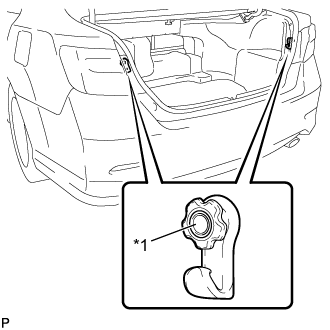 |
Engage the 2 pins to install the 2 No. 1 luggage compartment trim hooks.
| *1 | Pin |
| 36. INSTALL REAR FLOOR FINISH PLATE |
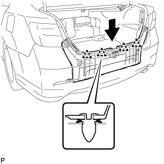 |
Engage the 4 clips and install the rear floor finish plate.
Install the 5 clips.
| 37. INSTALL SERVICE PLUG GRIP |