 |
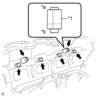
Install 4 new injector vibration insulators to the cylinder head.
| *1 | Fuel Delivery Spacer |
| *a | Fuel Delivery Pipe Side |
| *b | Cylinder Head Side |
INTAKE MANIFOLD > INSTALLATION |
| 1. SET INTAKE MANIFOLD |
Connect the fuel vapor feed hose to the intake manifold and slide the clip to secure it.
Install the vacuum hose and engage the clamp to the intake manifold.
Install the wire harness clamp bracket to the intake manifold with the bolt.
Install a new gasket to the intake manifold.
Set the intake manifold to the cylinder head sub-assembly.
| 2. INSTALL FUEL DELIVERY PIPE SUB-ASSEMBLY |
|
Install 4 new injector vibration insulators to the cylinder head.
| *1 | Fuel Delivery Spacer |
| *a | Fuel Delivery Pipe Side |
| *b | Cylinder Head Side |
Install the 2 fuel delivery spacers onto the cylinder head.
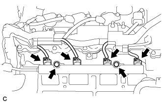 |
Install the fuel delivery pipe sub-assembly with the 4 fuel injector assemblies and install the 2 bolts.
Connect the 4 fuel injector connectors.
| 3. CONNECT FUEL TUBE SUB-ASSEMBLY |
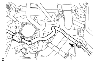 |
Push the tube connector onto the pipe until the tube connector makes a "click" sound.
Install the No. 1 fuel pipe clamp.
| 4. INSTALL INTAKE MANIFOLD |
Temporarily install the intake manifold to the cylinder head sub-assembly with the 6 bolts.
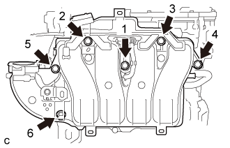 |
Tighten the 6 bolts in the order shown in the illustration.
Engage the 6 wire harness clamps to the intake manifold.
Connect the heated oxygen sensor connector.
Connect the No. 2 ventilation hose to the intake manifold and slide the clip to secure it.
| 5. INSTALL MANIFOLD ABSOLUTE PRESSURE SENSOR |
Install the manifold absolute pressure sensor with the bolt.
Connect the vacuum hose and connector.
| 6. INSTALL INTAKE FLANGE (w/o EGR System) |
Install a new gasket to the intake manifold.
Type A:
Install the intake flange to the intake manifold with the 4 bolts.
Type B:
Install the intake flange to the intake manifold with the 3 bolts.
| 7. INSTALL EGR VALVE ASSEMBLY (w/ EGR System) |
Install 2 new gaskets to the intake manifold and No. 1 EGR pipe.
Type A:
Temporarily install the EGR valve assembly to the intake manifold with the 4 bolts.
Temporarily install the 2 nuts to the EGR valve assembly.
Tighten the 4 bolts.
Type B:
Temporarily install the EGR valve assembly to the intake manifold with the 3 bolts.
Temporarily install the 2 nuts to the EGR valve assembly.
Tighten the 3 bolts.
Using a 12 mm deep socket wrench, tighten the 2 nuts.
Using a 10 mm deep socket wrench, install the bolt to the EGR valve assembly.
Connect the 2 water by-pass hoses to the EGR valve assembly and slide the 2 clips to secure them.
Connect the EGR valve assembly connector.
| 8. INSTALL FRONT OUTER COWL TOP PANEL SUB-ASSEMBLY (for LHD) |
Install the front outer cowl top panel sub-assembly with the 10 bolts.
Engage the 2 clamps to install the wire harness to the front outer cowl top panel sub-assembly.
| 9. INSTALL FRONT OUTER COWL TOP PANEL SUB-ASSEMBLY (for RHD) |
Install the front outer cowl top panel sub-assembly with the 10 bolts.
Engage the 2 clamps to install the wire harness to the front outer cowl top panel sub-assembly.
Engage the 2 clamps to install the wire harness to the front outer cowl top panel sub-assembly.
| 10. INSTALL WINDSHIELD WIPER MOTOR AND LINK ASSEMBLY |
| 11. INSTALL THROTTLE WITH MOTOR BODY ASSEMBLY |
| 12. CONNECT CABLE TO NEGATIVE AUXILIARY BATTERY TERMINAL |
| 13. INSTALL LUGGAGE TRIM SERVICE HOLE COVER |
Engage the claw to connect the luggage trim service hole cover.
| 14. INSPECT FOR FUEL LEAK |
Check fuel pump operation.
Connect the intelligent tester to the DLC3.
Turn the power switch on (IG) and turn the intelligent tester on.
Enter the following menus: Powertrain / Engine and ECT / Active Test / Control the Fuel Pump / Speed.
Check for pressure in the fuel inlet tube from the fuel line. Check that sounds of fuel flowing from the fuel tank can be heard. If no sounds can be heard, check the integration relay, fuel pump, ECM and wiring connectors.
Inspect for fuel leaks.
Check that there are no fuel leaks from the fuel system after doing any maintenance or repairs. If there is a fuel leak, repair or replace parts as necessary.
Turn the power switch off.
Disconnect the intelligent tester from the DLC3.