 |
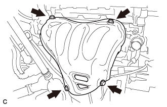
Remove the 4 bolts and No. 1 exhaust manifold heat insulator from the exhaust manifold converter sub-assembly (TWC: Front Catalyst).
CYLINDER HEAD GASKET > REMOVAL |
| 1. REMOVE TIMING CHAIN COVER SUB-ASSEMBLY |
| 2. REMOVE NO. 1 EXHAUST MANIFOLD HEAT INSULATOR |
|
Remove the 4 bolts and No. 1 exhaust manifold heat insulator from the exhaust manifold converter sub-assembly (TWC: Front Catalyst).
| 3. DISCONNECT NO. 1 WATER BY-PASS HOSE |
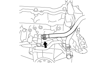 |
Slide the clamp and disconnect the No. 1 water by-pass hose from the cylinder head sub-assembly.
| 4. REMOVE THROTTLE WITH MOTOR BODY ASSEMBLY |
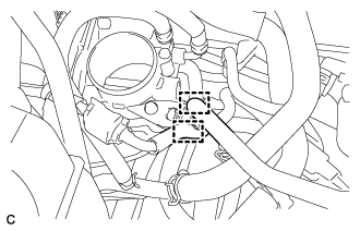 |
Disconnect the 2 hoses.
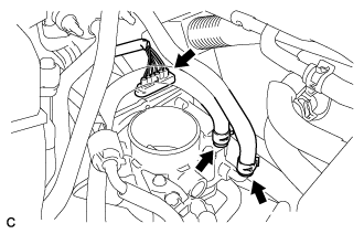 |
Disconnect the throttle body connector.
Disconnect the 2 water by-pass hoses from the throttle with motor body assembly.
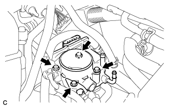 |
Remove the 4 bolts and the throttle body with fuel tube bracket.
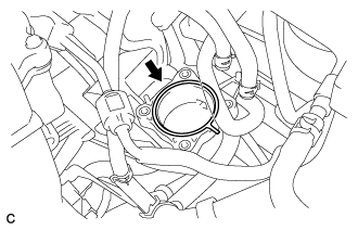 |
Remove the gasket from the intake manifold.
| 5. REMOVE NO. 2 EGR PIPE (w/ EGR System) |
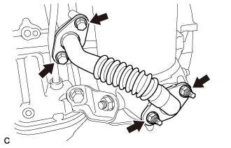 |
Remove the 2 bolts, 2 nuts and No. 2 EGR pipe from the exhaust manifold converter sub-assembly (TWC: Front Catalyst) and EGR cooler assembly.
Remove the 2 gaskets from the No. 2 EGR pipe.
| 6. REMOVE MANIFOLD STAY |
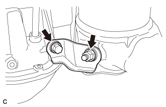 |
Remove the bolt, nut and manifold stay from the exhaust manifold converter sub-assembly (TWC: Front Catalyst) and stiffening crankcase assembly.
| 7. REMOVE NO. 2 MANIFOLD STAY |
|
Remove the 2 bolts, 2 nuts and No. 2 EGR pipe from the exhaust manifold converter sub-assembly (TWC: Front Catalyst) and EGR cooler assembly.
Remove the 2 gaskets from the No. 2 EGR pipe.
| 8. REMOVE EXHAUST MANIFOLD CONVERTER SUB-ASSEMBLY |
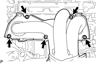 |
Remove the 5 nuts and exhaust manifold converter sub-assembly (TWC: Front Catalyst) from the cylinder head sub-assembly.
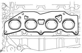 |
Remove the gasket from the cylinder head sub-assembly.
| 9. REMOVE EGR COOLER ASSEMBLY (w/ EGR System) |
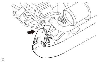 |
Slide the clip and disconnect the water by-pass hose from the EGR cooler assembly.
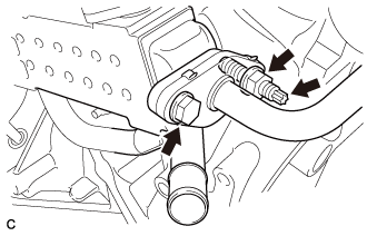 |
Remove the bolt and nut and separate the No. 1 EGR pipe.
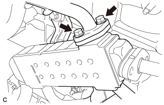
Using an E8 "TORX" socket wrench, remove the stud bolt from the EGR cooler assembly.
 |
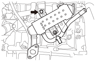
Remove the 2 bolts and separate the No. 1 water by-pass pipe.
 |
Remove the bolt, nut and EGR cooler assembly from the cylinder block.
 | Bolt |
 | Nut |
Remove the 2 gaskets from the EGR cooler assembly.
| 10. REMOVE NO. 1 EGR PIPE (w/ EGR System) |
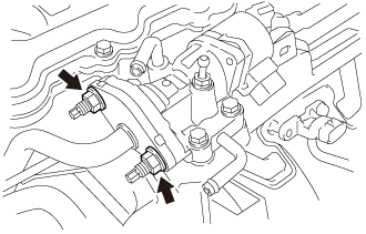 |
Remove the 2 nuts.
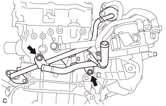 |
Remove the 2 bolts, No. 1 EGR pipe and gasket.
| 11. REMOVE NO. 3 WATER BY-PASS PIPE (w/o EGR System) |
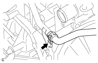 |
Slide the clip and disconnect the No. 5 water by-pass hose from the No. 3 water by-pass pipe.
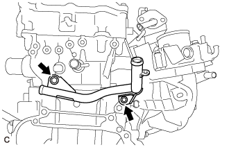 |
Remove the 2 bolts and No. 3 water by-pass pipe.
| 12. REMOVE NO. 1 WATER BY-PASS PIPE (w/o EGR System) |
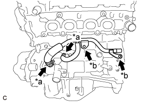 |
Separate the 2 clamps.
| *a | Clamp |
| *b | Bolt |
Slide the 2 clamps and remove the No. 4 water by-pass hose and No. 6 water by-pass hose from the No. 1 water by-pass pipe.
Remove the 2 bolts and No. 1 water by-pass pipe.
| 13. REMOVE FUEL DELIVERY PIPE SUB-ASSEMBLY |
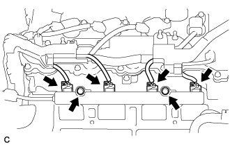 |
Disconnect the 4 fuel injector connectors.
Remove the 2 bolts, and then remove the fuel delivery pipe together with the 4 fuel injectors.
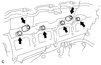 |
Remove the 2 fuel delivery spacers from the cylinder head.
Remove the 4 injector vibration insulators from the cylinder head.
| 14. REMOVE INTAKE MANIFOLD |
Remove the intake manifold from the cylinder head sub-assembly.
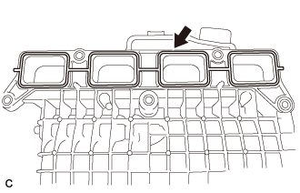 |
Remove the gasket from the intake manifold.
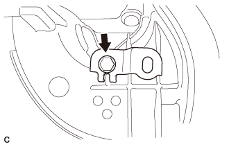 |
Remove the bolt and wire harness clamp bracket from the intake manifold.
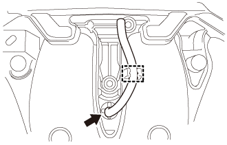 |
Disengage the clamp and remove the vacuum hose from the intake manifold.
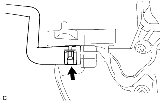 |
Slide the clip and disconnect the fuel vapor feed hose from the intake manifold.
| 15. SET NO. 1 CYLINDER TO TDC/COMPRESSION |
Temporarily install the crankshaft pulley bolt.
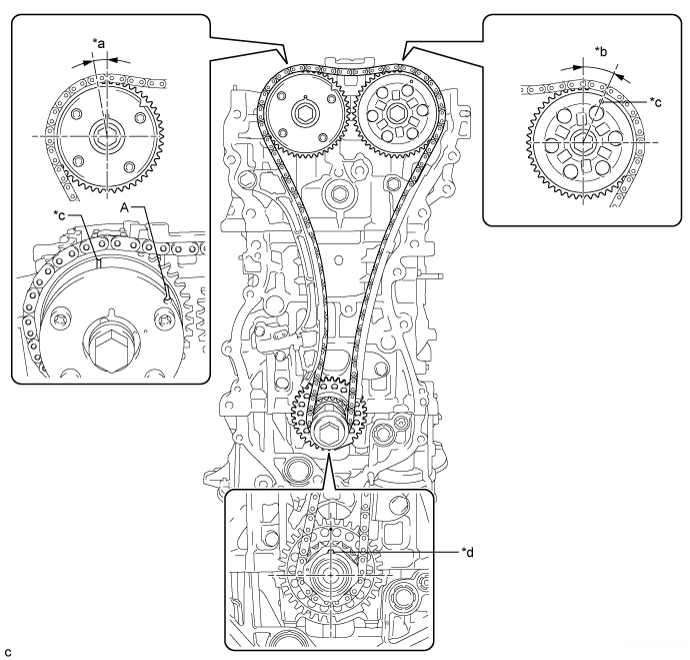
| *a | Approximately 7° | *b | Approximately 32° |
| *c | Timing Mark | *d | Key |
Rotate the crankshaft clockwise so that the timing marks on the crankshaft timing gear and camshaft timing gears are as shown in the illustration.
Remove the crankshaft pulley bolt.
| 16. REMOVE TIMING CHAIN GUIDE |
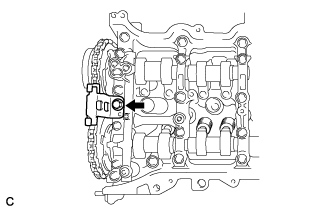 |
Remove the bolt and timing chain guide.
| 17. REMOVE NO. 1 CHAIN TENSIONER ASSEMBLY |
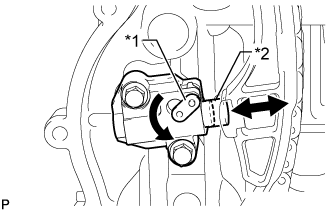 |
Allow the plunger to extend slightly, and then rotate the stopper plate counterclockwise to release the lock. Once the lock is released, push the plunger into the tensioner.
| *1 | Stopper Plate |
| *2 | Plunger |
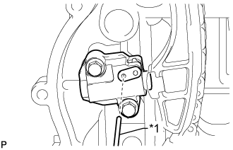 |
Move the stopper plate clockwise to set the lock, and insert a pin into the stopper plate hole.
| *1 | Pin |
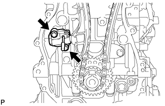 |
Remove the 2 bolts, chain tensioner and gasket.
| 18. REMOVE CHAIN TENSIONER SLIPPER |
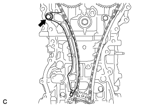 |
Remove the bolt and chain tensioner slipper.
| 19. REMOVE CHAIN SUB-ASSEMBLY |
Remove the chain sub-assembly.
| 20. REMOVE NO. 1 CHAIN VIBRATION DAMPER |
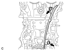 |
Remove the 2 bolts and chain vibration damper.
| 21. REMOVE CAMSHAFT TIMING GEAR ASSEMBLY |
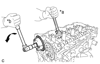 |
Hold the hexagonal portion of the camshaft with a wrench and remove the bolt and camshaft timing gear.
| *a | Hold |
| *b | Turn |
| 22. REMOVE CAMSHAFT TIMING SPROCKET |
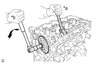 |
Hold the hexagonal portion of the camshaft with a wrench and remove the bolt and camshaft timing sprocket.
| *a | Hold |
| *b | Turn |
| 23. REMOVE CAMSHAFT HOUSING SUB-ASSEMBLY |
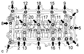 |
Uniformly loosen and remove the 20 bearing cap bolts in the sequence shown in the illustration.
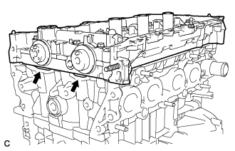 |
Remove the camshaft housing by prying between the cylinder head and camshaft housing with a screwdriver.
| 24. REMOVE CAMSHAFT BEARING CAP |
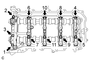 |
Remove the 11 bearing cap bolts in the sequence shown in the illustration.
Remove the 5 bearing caps.
| 25. REMOVE OIL CONTROL VALVE FILTER |
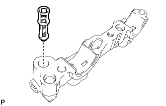 |
Remove the oil control valve filter from the No. 1 camshaft bearing cap.
| 26. REMOVE NO. 1 CAMSHAFT BEARING |
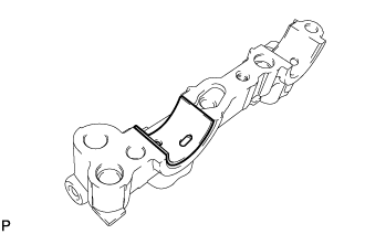 |
Remove the No. 1 camshaft bearing from the No. 1 camshaft bearing cap.
| 27. REMOVE CAMSHAFT |
Remove the camshaft and No. 2 camshaft.
| 28. REMOVE NO. 2 CAMSHAFT BEARING |
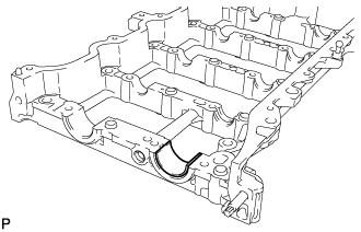 |
Remove the No. 2 camshaft bearing from the camshaft housing sub-assembly.
| 29. REMOVE NO. 1 VALVE ROCKER ARM SUB-ASSEMBLY |
Remove the 16 valve rocker arms from the cylinder head.
| 30. REMOVE VALVE LASH ADJUSTER ASSEMBLY |
Remove the 16 valve lash adjusters from the cylinder head.
| 31. REMOVE VALVE STEM CAP |
Remove the 16 valve stem caps from the cylinder head.
| 32. REMOVE CYLINDER HEAD SUB-ASSEMBLY |
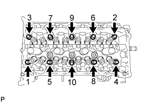 |
Using a 10 mm bi-hexagon wrench, uniformly loosen the 10 bolts in the sequence shown in the illustration. Remove the 10 cylinder head bolts and plate washers.
Remove the cylinder head.
| 33. REMOVE CYLINDER HEAD GASKET |
Remove the cylinder head gasket from the cylinder block.