 |
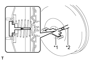
Place the accessory tool on the brake booster assembly.
| *1 | Accessory Tool |
| *2 | Brake Booster Push Rod |
BRAKE MASTER CYLINDER (for LHD) > INSTALLATION |
| 1. INSPECT AND ADJUST BRAKE BOOSTER PUSH ROD (for TMMK Made) |
Apply chalk to the tip of the accessory tool.
|
Place the accessory tool on the brake booster assembly.
| *1 | Accessory Tool |
| *2 | Brake Booster Push Rod |
Measure the clearance between the brake booster push rod and accessory tool.
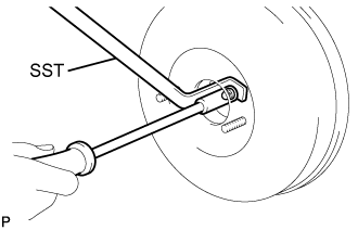 |
If the clearance is not as specified, adjust the push rod length by holding the rod using SST and turning the tip of the rod using a socket driver (7 mm).
| 2. INSTALL BRAKE MASTER CYLINDER O-RING |
Install a new brake master cylinder O-ring to the brake master cylinder sub-assembly.
| 3. INSTALL BRAKE MASTER CYLINDER SUB-ASSEMBLY (for TMC, TMMR Made) |
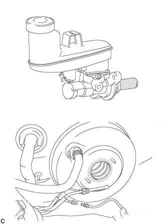 |
Apply a light layer of a grease enclosed with a new brake master cylinder sub-assembly or lithium soap base glycol grease to the circumference of the brake master cylinder sub-assembly and inner surface of the brake booster assembly as shown in the illustration.
 | Apply Grease |
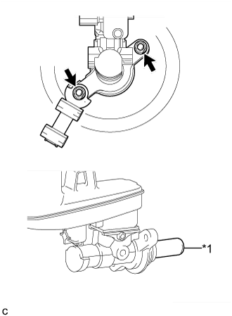 |
Install the brake master cylinder sub-assembly and front No. 1 brake tube way to the brake booster assembly with the 2 nuts.
| *1 | Master Cylinder Piston |
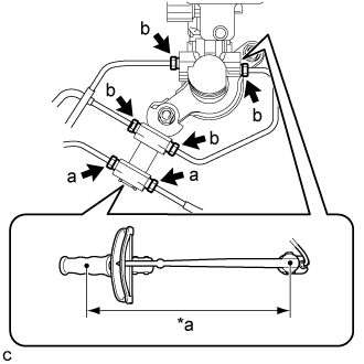 |
Using a union nut wrench, connect the 6 brake lines and install the brake master cylinder to way tube to the brake master cylinder sub-assembly.
| *a | Torque Wrench Fulcrum Length |
Connect the reservoir level switch connector and engage the clamp.
| 4. INSTALL BRAKE MASTER CYLINDER SUB-ASSEMBLY (for TMMK Made) |
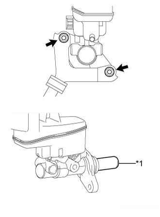 |
Install the brake master cylinder sub-assembly and front No. 1 brake tube way to the brake booster assembly with the 2 nuts.
| *1 | Master Cylinder Piston |
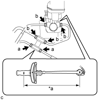 |
Using a union nut wrench, connect the 6 brake lines and install the brake master cylinder to way tube to the brake master cylinder sub-assembly.
| *a | Torque Wrench Fulcrum Length |
Connect the reservoir level switch connector and engage the clamp.
| 5. BLEED BRAKE SYSTEM |
| 6. INSTALL AIR CLEANER CASE SUB-ASSEMBLY (for 6AR-FSE) |
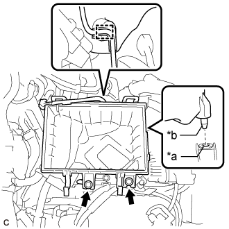 |
Insert the projection of the air cleaner case sub-assembly into the hole of the No. 1 air cleaner bracket as shown in the illustration.
| *a | Hole |
| *b | Projection |
Install the 2 bolts.
Connect the wire harness clamp.
| 7. INSTALL AIR CLEANER FILTER ELEMENT SUB-ASSEMBLY (for 6AR-FSE) |
Install the air cleaner filter element sub-assembly to the air cleaner case sub-assembly.
| 8. INSTALL AIR CLEANER CAP WITH AIR CLEANER HOSE (for 6AR-FSE) |
Connect the air cleaner cap with air cleaner hose to the throttle body with motor assembly.
Install the air cleaner cap with air cleaner hose with the 2 guides and 2 air cleaner cap clamps.
Tighten the hose clamp.
Connect the union to connector tube hose to the air cleaner hose sub-assembly.
Engage the wire harness clamp.
Connect the mass air flow meter sub-assembly connector.
Engage the ventilation hose clamp.
Connect the ventilation hose to the cylinder head cover sub-assembly and slide the clip to secure it.
| 9. INSTALL INLET AIR CLEANER ASSEMBLY (for 6AR-FSE) |
Install the inlet air cleaner assembly with the 2 bolts.
| 10. INSTALL NO. 1 ENGINE COVER SUB-ASSEMBLY (for 6AR-FSE) |
Engage the 3 grommets to install the No. 1 engine cover sub-assembly.
| 11. INSTALL AIR CLEANER CASE SUB-ASSEMBLY (for 2AR-FE) |
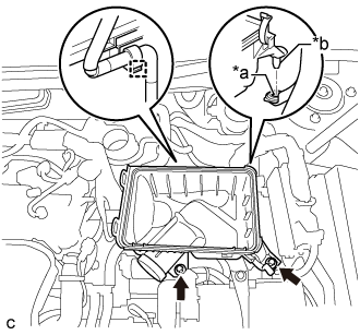 |
Insert the projection of the air cleaner case sub-assembly to the hole of the No. 2 air cleaner bracket as shown in the illustration.
| *a | Wire harness clamp |
| *b | Hole |
| *c | Projection |
Tighten the 2 bolts.
Connect the wire harness clamp.
| 12. INSTALL AIR CLEANER FILTER ELEMENT SUB-ASSEMBLY (for 2AR-FE) |
| 13. INSTALL AIR CLEANER CAP SUB-ASSEMBLY (for 2AR-FE) |
Install the air cleaner cap sub-assembly with the 2 clamps.
Install the air cleaner hose with the hose clamp.
Connect the ventilation hose to the cylinder head cover.
Install the fuel vapor feed hose to the air cleaner hose.
Connect the mass air flow meter connector and 2 wire harness clamps to the air cleaner cap sub-assembly.
Connect the vacuum switching valve assembly to the air cleaner hose.
| 14. INSTALL INLET AIR CLEANER ASSEMBLY (for 2AR-FE) |
Install the inlet air cleaner with the 2 bolts.
| 15. INSTALL AIR CLEANER CASE SUB-ASSEMBLY (for 2GR-FE) |
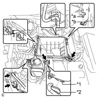 |
Install the air cleaner case sub-assembly to the inlet No. 1 air cleaner.
Insert the projection of the air cleaner case sub-assembly to the hole of the No. 2 air cleaner bracket as shown in the illustration.
| *1 | Air Cleaner Case Sub-assembly |
| *2 | Inlet No. 1 Air Cleaner |
| *a | Projection |
| *b | Hole |
Tighten the 2 bolts.
Connect the wire harness clamp, connector, vacuum hose and No. 1 fuel vapor feed hose.
| 16. INSTALL AIR CLEANER FILTER ELEMENT SUB-ASSEMBLY (for 2GR-FE) |
| 17. INSTALL AIR CLEANER CAP SUB-ASSEMBLY (for 2GR-FE) |
Connect the air cleaner cap sub-assembly to the throttle with motor body assembly with the hose clamp.
Install the air cleaner cap with hose to the air cleaner case with the 2 clamps.
Connect the wire harness clamp and mass air flow meter connector.
Connect the 3 hoses.
Connect the ventilation hose.
Connect the mass air flow meter connector and wire harness clamp.
| 18. INSTALL INLET NO. 2 AIR CLEANER (for 2GR-FE) |
Install the inlet No. 2 air cleaner to the air cleaner case sub-assembly with the 2 bolts.
Connect the 2 wire harness clamps and vacuum hose clamp.
| 19. INSTALL COOL AIR INTAKE DUCT SEAL (for TMC, TMMR Made) |
Install the cool air intake duct seal with the 9 clips.
| 20. REMOVE COOL AIR INTAKE DUCT SEAL (for TMMK Made) |
Install the cool air intake duct seal with the 9 clips.
| 21. INSTALL FRONT OUTER COWL TOP PANEL SUB-ASSEMBLY |
Install the front outer cowl top panel sub-assembly with the 10 bolts.
Engage the 2 clamps to install the wire harness to the front outer cowl top panel sub-assembly.
w/ Windshield Deicer System:
Connect the connector.
Engage the 2 clamps to install the wire harness to the front outer cowl top panel sub-assembly.
w/ Heated Windshield Defroster System:
Connect the 2 connectors.
Engage the 4 clamps to install the wire harness to the front outer cowl top panel sub-assembly.
| 22. INSTALL WINDSHIELD WIPER MOTOR AND LINK ASSEMBLY |